
TM 5-2420-230-24-1
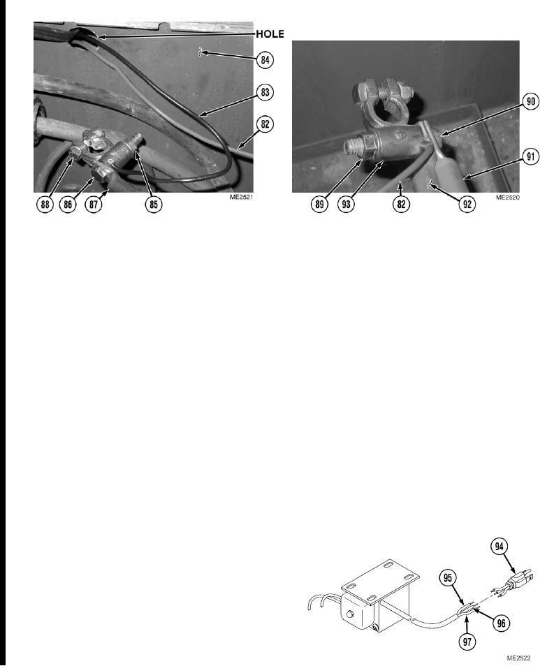
c. Trickle Charger
(1)
Route red trickle charger wire (82) and black trickle charger wire (83) through hole in battery box (84).
NOTE
Cables removed and installed in Steps (2) through (5) are battery-to-electrical master switch,
battery-to-NATO slave receptacle, and battery-to-starter solenoid cables.
Tag all cables and note their positions before removal. Ensure all cables are reconnected to
positions noted prior to removal.
(2)
Remove nut (85), screw (86), and cable (87) from negative (-) terminal (88).
(3)
Install cable (87) and black trickle charger wire (83) on negative (-) terminal (88) with screw (86) and nut (85).
(4)
Remove nut (89), screw (90), cable (91), and cable (92) from positive (+) terminal (93).
(5)
Install cable (92), cable (91), and red trickle charger wire (82) on positive (+) terminal (93) with screw (90) and
nut (89).
NOTE
Cut as close to electrical outlet plug as possible.
(6)
Cut electrical outlet plug (94) from three
trickle charger wires (95), (96), and (97).
Discard electrical outlet plug.
(7)
Remove 0.25 in. (6 mm) of insulation from
end of three trickle charger wires (95), (96),
and (97).
Change 1
20-10

