
TM 5-2420-230-24-1
Maintenance & Service Manual
R & HR32000 3 & 6 Speed LD
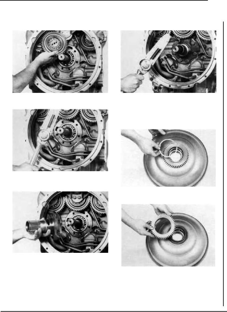
Figure 271
Figure 274
Install pump drive gears.
Install support bolts and tighten to specified torque. (See torque
chart).
DISASSEMBLY AND REASSEMBLY
OF IMPELLER AND BAFFLE
DISASSEMBLY
Figure 272
Tighten pump drive gear support bolts to specified torque. (See
torque chart).
Figure 275
Remove pump drive gear retainer ring.
Figure 273
Install new sealing ring expander spring and oil sealing ring on
support. NOTE: Expander spring gap to be 180 from sealing
ring hook joint. Position support on turbine shaft, turn support
Figure 276
to clear pump drive gear. Align support holes with converter
Remove pump drive gear.
housing.
--47--

