
TM 5-2420-230-24-1
4.
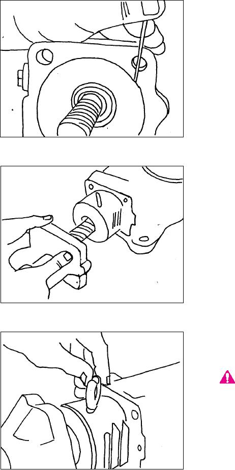
Install a new seal ring on the bearing cap and
actuating shaft assembly (Figure 123).
NOTE:
Cover the new seal ring with a light coat of
grease to keep it in place during assembly.
Figure 123
5.
Insert the bearing cap and actuating
shaft assembly into the piston as shown
(Figure 124).
NOTE:
Do not insert the bearing cap assembly com-
pletely. The bearing cap must be inserted to
within 3" of the end of the piston.
Figure 124
6. Install both halves of the ball guide into
the ball guide cavity (Figure 125).
CAUTION
Make sure the ball guides are pushed into the
cavity all the way. Failure to do so during
installation will result in the ball guides being
pushed out of the piston during assembly. This
will cause the balls to come out of their track
and binding will result.
Figure 125
K-90

