
TM 5-2420-230-24-2
B3.9 and B5.9 Series Engines
Flow Diagram, Cooling System
Section 8 - Cooling System - Group 08
Page 8-3
Flow Diagram, Cooling System
CAUTION
Never operate the engine without a thermostat. Without a thermostat, the coolant will not flow to the radiator
and the engine will overheat.
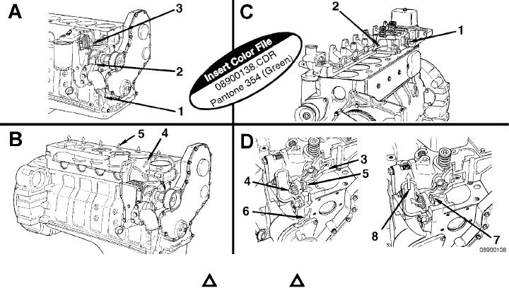
The illustration identifies the significant features of the coolant system.
Sections A and B.
Coolant is drawn from the radiator by the integrally mounted water pump. The output from the water pump empties
into the oil cooler cavity of the cylinder block.
The coolant then circulates around each cylinder and crosses the block to the fuel pump side of the engine.
4. Coolant Flow Past Cylinder Head
1. Coolant Inlet
5. Coolant to Cylinder Head
2. Pump Impeller
3. Coolant Flow Past Oil Cooler
Sections C and D.
Coolant then flows up into the cylinder head, crosses over the valve bridges, and down the exhaust manifold side of
the engine to the integral thermostat housing.
As the coolant flows across the head toward the thermostat housing, it provides cooling for the injector. When the engine
is below operating temperature, the thermostat is closed, and the coolant flow bypasses the radiator and goes to the
water pump inlet through internal drillings in the block and cylinder head.
1. Coolant Flow from the Cylinder Head
5. Coolant Bypass Passage
2. Coolant to the Thermostat Housing
6. Coolant Flow to Pump Inlet
3. Coolant Flow Past Injector
7. Bypass Closed
4. Thermostat
8. Coolant Flow Back to Radiator
When operating temperature is reached, the thermostat opens, blocking the bypass passage to the water pump and
opening the outlet to the radiator.
L-1059

