
TM 5-2420-232-10
0004
AUXILIARY HYDRAULIC CIRCUIT (HAND TOOLS) CONTINUED
External (Emergency) Deactivation Switch
0004
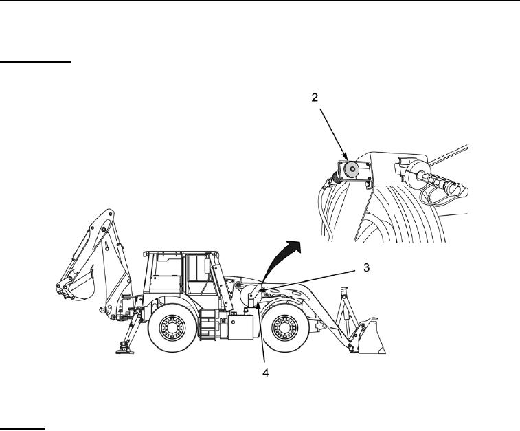
Switch Location. The deactivation switch (Figure 101, Item 2) is located on the hose reel bracket (Figure 101, Item 3) on the
right-hand side of the machine.
435-A0314
Figure 101. Switch Location
04
Operation.
1. Deactivate Circuit (Using External Deactivation Switch). To deactivate the hydraulic service, push the switch (Figure
101, Item 2) in. The hydraulic circuit will be deactivated. The pressure in the hoses will be vented to tank.
2.
Reactivate the Circuit.
NOTE
If the external deactivation switch is used, the following procedure must be used to reactivate the
system. Simply pulling out the external deactivation switch will not reactivate the system.
a.
Pull the switch (Figure 101, Item 2) out. This will reset the external circuitry only; it will not reactivate the circuit.
b.
Operate the circuit activation switch as described above (Enable Auxiliary Hydraulic Circuit [Hand Tools]).
0004-105
Change 1

