
TM 5-3805-280-24-1
Theory of Operation
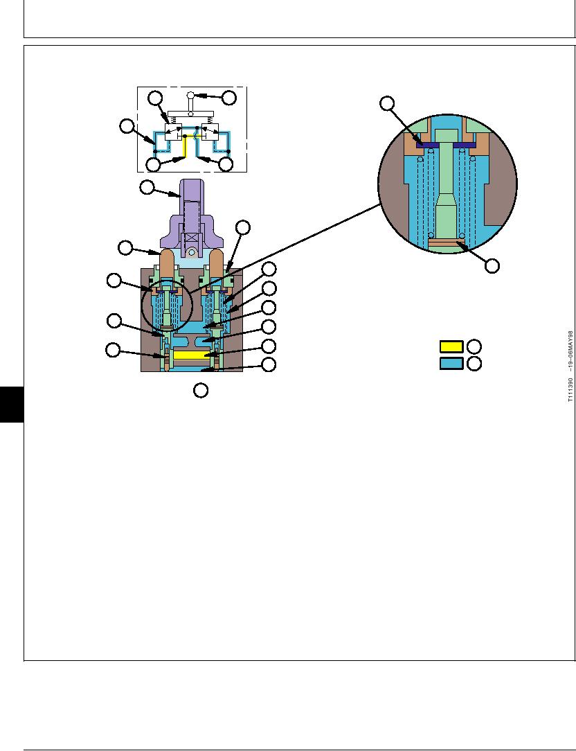
PILOT CONTROLLER OPERATION--NEUTRAL
E
B
N RETAINER
J
I
K
LEVER E
F SLEEVE
PLUNGER D
O SHIMS
G BALANCE SPRING
SPRING C
H RETURN SPRING
GUIDE
I TO RESERVOIR
SPOOL B
J TO CONTROL VALVE
K FROM PILOT PUMP
L PILOT OIL
PISTON A
M RETURN OIL
I TO HYDRAULIC OIL TANK
T111390
P PILOT CONTROLLER - NEUTRAL
9025
05
6
factory for correct operation of the controller. The
Two hand-operated pilot controllers (right and left) are
balance and return springs used in ports 1 and 3 are
used to control the dig functions. Each controller
different than the balance and return springs used in
assembly contains four valve assemblies, one for each
ports 2 and 4. The port numbers are stamped on the
direction of each function.
housing.
The pilot controller consists of the plunger (D), sleeve
In neutral (P), the spool is pushed up by the return
(F), spring guide (C), retainer (N), spool (B), piston (A),
spring to block oil from the pilot pump (K) to control
balance spring (G), shims (O), and return spring (H).
valve (J) pilot cap. With the spool up, the passage to
The spools are select fitted to the bores in the
the control valve pilot cap is connected to the hydraulic
housing. The quantity of shims for each balance spring
oil tank (I).
and spool assembly has been determined at the
TX,9025,GG2285
1922APR981/1
6-6

