
TM 5-3805-280-24-1
Theory of Operation
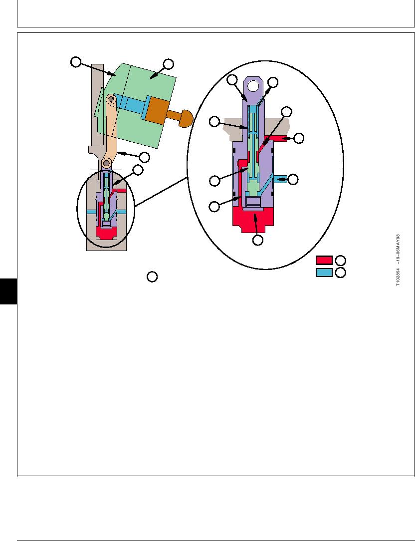
PROPEL MOTOR SLOW SPEED OPERATION
VALVE A
B ROTARY
PLATE
GROUP
D
H
TO MOTOR
SERVO
CASE DRAIN
PISTON
I
CHAMBER
G
"A"
SPRING
J
FROM
MOTOR
C LINK
PORT
D SERVO
PISTON
K
F
FROM PROPEL
SPOOL
SPEED CHANGE
SOLENOID
E
VALVE
ORIFICE
L
CHAMBER "B"
M SUPPLY OIL
N RETURN OIL
T102854
O SLOW SPEED
9025
05
74
Supply oil from motor port (J) is now applied to both
The servo piston (D) is connected by a link (C) to the
chamber "A" (I) and chamber "B" (L) at the same time.
valve plate (A). When servo piston is extended or
Supply oil pressure in chamber "B" acts on a larger
retracted by supply oil pressure the angle of the rotary
area than the supply oil pressure in chamber "A"
group (B) changes and the propel speed changes
causing the servo piston to move upward increasing
accordingly.
rotary group swash angle. As the swash angle
increases, the stroke of each piston is increased
When propel speed is set to slow speed the bottom of
resulting in slower revolution of the propel motor for
speed selector valve spool (F) is open to return
slower propel speed. (See Propel Motor Fast Speed
through the propel speed change solenoid valve. The
Operation in this group.)
spool (F) is pushed down by the spring (G). (For
operation of propel speed change solenoid valve, see
Proportional Solenoid Valve Operation in this group.
For circuit operation, see Propel Motor Speed Change
Circuit Operation in this group.)
TX,05,GG2168 1920MAY981/1
6-70

