
TM 5-3805-280-24-1
Tests
EXCAVATOR DIAGNOSTICS PROGRAM--
MONITOR DATA ITEMS
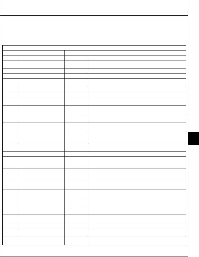
NOTE: This chart lists engine and pump controller
dynamic data items that can be monitored by the
excavator diagnostics program.
230LCR EXCAVATOR MONITOR DATA ITEMS
Item
Display List
Units
Description
1
Front pump control pressure
psi
Pilot signal from the front pump control valve to pump regulator
2
EC angle
V
Feedback signal from the engine control sensor to the engine and pump
controller
3
Front pump delivery pressure
psi
Pump supply pressure at front pump outlet.
4
Rear pump delivery pressure
psi
Pump supply pressure at rear pump outlet.
5
Arm in pilot pressure
psi
Pilot pressure from pilot controller to control valve pilot cap. Pressure
measured at flow regulator valve.
6
Rear pump control pressure
psi
Pilot signal from rear pump control valve to pump regulator.
8
RPM dial angle
V
Electrical signal from engine rpm dial.
9
Arm regenerative control
psi
Pilot pressure from arm regenerative solenoid valve to arm regenerative
pressure
valve in left control valve. A calculated pressure, not actual pressure.
10
Propel motor control pressure
psi
Pilot pressure from propel speed change solenoid valve to speed selector
valve in propel motors. A calculated pressure, not actual pressure.
11
Speed sense control pressure
psi
Pilot pressure from speed sense solenoid valve to front and rear pump
regulators. A calculated pressure, not actual pressure.
12
Power boost control pressure
psi
Pilot pressure from power boost solenoid valve to the piston in the
system relief valve. This is a calculated pressure, not the actual pressure.
13
Target engine speed
rpm
Set by engine rpm dial. Target speed for engine pull down when under
9025
load. (Approximately 150 rpm difference from engine speed under no
25
load.)
21
14
Actual engine speed
rpm
Engine speed sensed by engine speed sensor. Sensor is located in the
pump drive gearbox adjacent to front pump.
15
EC motor position
steps
Electrical signal from engine and pump controller to engine control motor.
20
Pressure switch
Boom Up, Dig,
Electrical signal from pressure switches to engine and pump controller
Propel
when function is actuated. Boom up is located on flow regulator valve.
Dig and propel are located on control valve.
21
Selected work mode switch
Dig, Grading,
Signal from control module to engine and pump controller for selected
Precision,
work mode.
Attachment
22
E mode switch
On, Off
Signal from control module to engine and pump controller for preset
engine speed.
23
Auto-idle switch
On, Off
Signal from control module to engine and pump controller to actuate
auto-idle function.
24
HP mode switch
On, Off
Signal from control module to engine and pump controller to actuate High
power mode.
25
Power boost switch
On, Off
Signal from power boost switch, in right control lever, to engine and pump
controller to actuate power boost function.
26
Selected propel speed switch
Fast, Slow
Signal from control module to engine and pump controller to change
propel speed.
27
Key switch
On, Off
Signal from key switch to engine and pump controller.
28
Engine learning control
Done, Undone,
Engine and pump controller has to be originally matched to each
Interruption
machine. See engine learning procedure.
29
Attachment mode pressure
On, Off
Signal to engine and pump controller when attachment mode is active.
switch
TX,9025,GG2677 1920MAY981/1
6-151

