
TM 5-3805-280-24-1
Tests
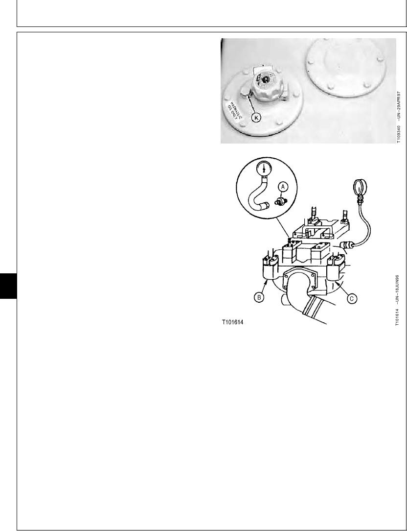
If laptop computer is not available, use the digital
pressure and temperature analyzer, and transducers or
gauges.
a. Stop the engine.
b. Loosen vent plug (K) to release the air pressure in
hydraulic oil tank.
c. Install adapter (A) and male quick coupler to test
port on front pump (C) or rear pump (B). Connect
the analyzer and transducers or gauges.
2. Install the temperature probe on the hydraulic oil
tank-to-pump suction line. (See JT05800 Digital
Thermometer Installation in this group.)
3. Raise and lower boom to pressurize hydraulic oil tank.
4. Heat hydraulic oil to the specified temperature. (See
Hydraulic System Warm-Up Procedure in this group.)
Oil--Specification
Temperature ........................................................... 50 5C (120 10F)
5. Run machine at specification.
9025
25
Engine in Standard Mode--Specification
68
Speed ........................................................................................... Fast Idle
Work Mode Selector--Specification
Position ........................................................................................ Dig Mode
A--Adapter
E Mode Switch--Specification
B--Rear Pump
C--Front Pump
Position .................................................................................................. Off
K--Vent Plug
HP Mode Switch--Specification
Position .................................................................................................. Off
Auto-Idle Switch--Specification
Position .................................................................................................. Off
6. Actuate the arm in function over relief.
Continued on next page
TX,9025,GG2648 1908JUN983/5
6-199

