
TM 5-3805-280-24-2
Fuel System
35
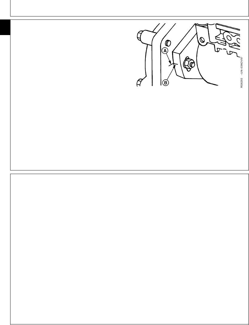
9. Check to make sure that timing marks on back side of
36
front plate (A) and injection pump flange (B) are
present and properly aligned. This assures that
repaired or replacement pump can be properly timed to
engine when installed.
If timing mark is not clearly visible on front plate, scribe
a visible reference mark as accurately as possible
in-line with mark on pump flange.
10. Remove three injection pump mounting stud nuts.
Remove injection pump from mounting studs. Place
pump on a clean flat surface and inspect shaft O.D.
A--Timing Mark on Front Plate
and drive gear as outlined later in this group. (See
B--Timing Mark on Pump
INSPECT INJECTION PUMP DRIVE GEAR I.D. AND
SHAFT O.D. later in this group).
RG,35,JW7609
1920NOV973/3
INSPECT INJECTION PUMP DRIVE GEAR I.D. AND SHAFT O.D.
IMPORTANT: When replacing injection pump drive
IMPORTANT: Use a good light source to
gear or installing a new pump, the
thoroughly inspect gear I.D. and
tapered surfaces of the pump drive
shaft O.D.
shaft O.D. and drive gear I.D. MUST
1. Inspect injection pump drive gear I.D. full 360 for
BE cleaned to remove protective
coatings and oily residue. Use a
metal transfer as a result of slippage on shaft.
suitable cleaner that does not leave
2. Inspect injection pump drive shaft O.D. full 360 for
a residue. Mating surfaces MUST BE
ASSEMBLED DRY and LUBRICANTS
presence of metal transfer from gear slippage. Also,
MUST NOT BE USED.
check to see if index pin in shaft is not damaged,
indicating gear slippage. If there is clear evidence
of metal transfer on pump shaft O.D., in drive gear
I.D., or if index pin in pump shaft is damaged,
injection pump and drive gear MUST BE replaced.
RG,35,JW7608
1920NOV971/1
13-415

