
TM 5-3805-280-24-2
Engine System Operation and Tests
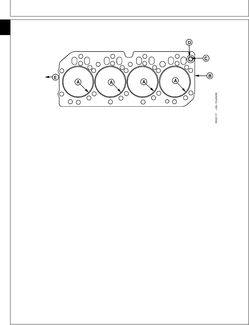
HEAD GASKET INSPECTION AND REPAIR SEQUENCE
105
16
A--Combustion Seals
B--Gasket Body
D--Elastomer Beading
E--Front of Engine
(Flanges)
C--Rocker Arm Oil Port
Strip
Flange sealing pattern eccentric/contains voids.
The following inspection procedures are recommended
Discoloration of flange and adjacent body areas.
whenever a head gasket joint failure occurs, or when
Flange surfaces rough/abraided/channelled.
joint disassembly takes place.
Examine gasket body (B) for the following:
1. Review historical data relating to machine
operation, maintenance and repair, along with
Combustion gas erosion paths or soot deposits
diagnostic observations. Note all areas requiring
originating at combustion seals.
further inspection and analysis.
Extreme discoloration/hardening/embrittlement in
localized areas.
2. Remove rocker arm cover and check for presence
O-ring seal missing/damaged in port area (C).
of coolant in the oil.
Elastomer missing/damaged in port area (D).
Oil or coolant paths from port areas.
3. Record head cap screw torques prior to removal.
Localized areas of low compression.
Upon removal, check cap screw length differences.
6. Before cleaning components, inspect head, block,
4. Remove cylinder head using appropriate lifting
and liners for evidence of combustion gas and fluid
devices to prevent handling damage to head
leakage. Inspect cylinders and valve ports for
gasket. (See REMOVE CYLINDER HEAD in Group
unusual deposits.
05.)
7. Clean block, head, liners, and cap screws. (See
5. Observe surfaces of removed head gasket.
Groups 05 and 10.)
Examine combustion seals (A) for the following:
8. Proceed with the following dimensional checks and
Flange severed/expanded/cracked/deformed.
visual inspections:
Adjacent body area burned/eroded.
Fire ring severed/displaced/missing.
Cylinder Head (See Group 05.)
Continued on next page
RG,105,JW7656
1921NOV971/2
13-493

