
TM 5-3805-280-24-2
Wiring Harness and Switches
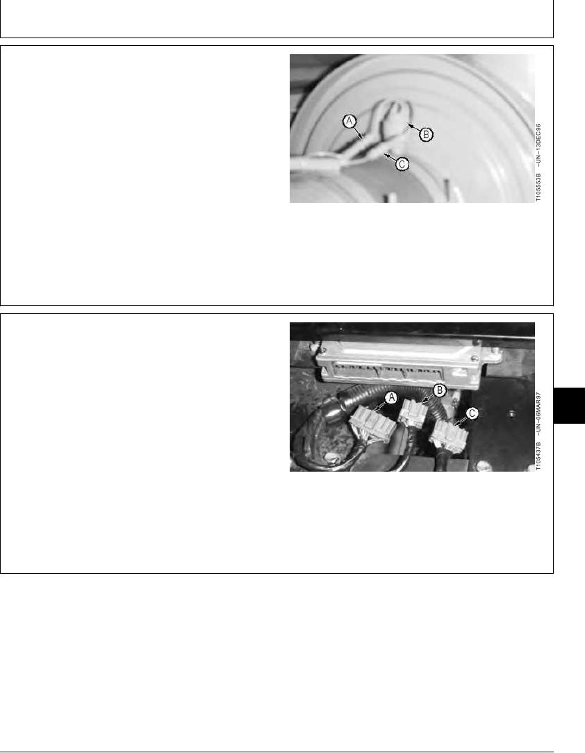
REMOVE AND INSTALL AIR CLEANER
RESTRICTION INDICATOR SWITCH
1. Disconnect connectors (A and C) to remove and
replace switch (B).
2. Install and tighten switch (B) and connect connectors
(A and C).
A--Connector
B--Switch
C--Connector
TX,16,UU3983
1919SEP981/1
CONNECTING ENGINE AND PUMP
CONTROLLER (EPC) HARNESS
CONNECTOR
IMPORTANT: Do not disconnect electrical connectors
16
while the engine is running. Damage to
1674
Engine and Pump Controller, or other
27
components may result. Disconnect
connectors only when instructed during
a test or check.
1. Push connectors into engine and pump controller.
A--Connector
2. Do Engine Speed Learning Procedure. (See procedure
B--Connector
in Group 1671.)
C--Connector
TX,16,UU3984
1919SEP981/1
16-58

