
TM 5-3805-280-24-2
Starting Circuit Theory of Operation
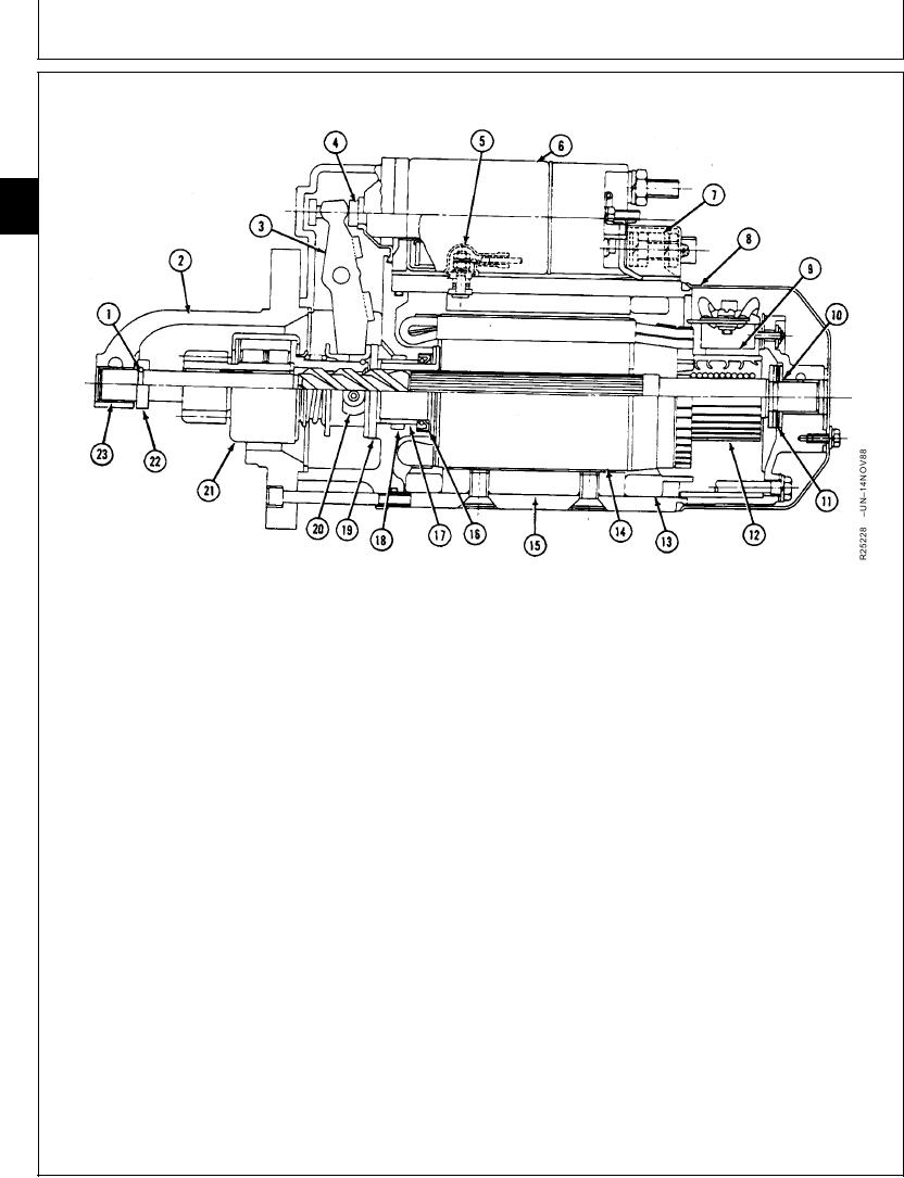
TYPICAL STARTING MOTOR OPERATION
60
05
2
1--Snap Ring
7--Field Connector
13--Field Windings
19--Brake Washer
2--Drive End Housing
8--End Frame Cover
14--Armature
20--Wear Pads
3--Shift Lever
9--Brush
15--Pole Shoe
21--Overrunning Clutch
4--Plunger
10--Bushing
16--Oil Seal
22--Pinion Stop
5--Shunt Field Terminal
11--Thrust Washer
17--Bushing
23--Bushing
6--Solenoid Assembly
12--Commutator
18--Felt
The two windings cancel each other, and solenoid is
When solenoid (6) engages, it pulls shift lever (3). Shift
released.
lever pushes overrunning clutch drive (21) to engage
pinion in stater gear on flywheel. As armature (14)
A spring pushes solenoid back to disengaged position.
turns, it cranks engine.
This opens main contacts and shuts off current to field
windings and armature.
When engine starters, overrunning clutch spins freely
on shaft. This prevents overspeeding of armature by
Shift lever retracts overrunning clutch drive,
flywheel.
disengaging pinion from flywheel. Brake washer (19)
slows armature to a stop.
When key switch is released, current to solenoid
hold-in winding is shut off. Current can feed through
both pull-in and hold-in windings from main contacts,
but direction of current is reversed in pull-in winding.
RG,RG34710,2337
1915Mar971/1
16-82

