
TM 5-3805-281-24-1
Hydraulic System
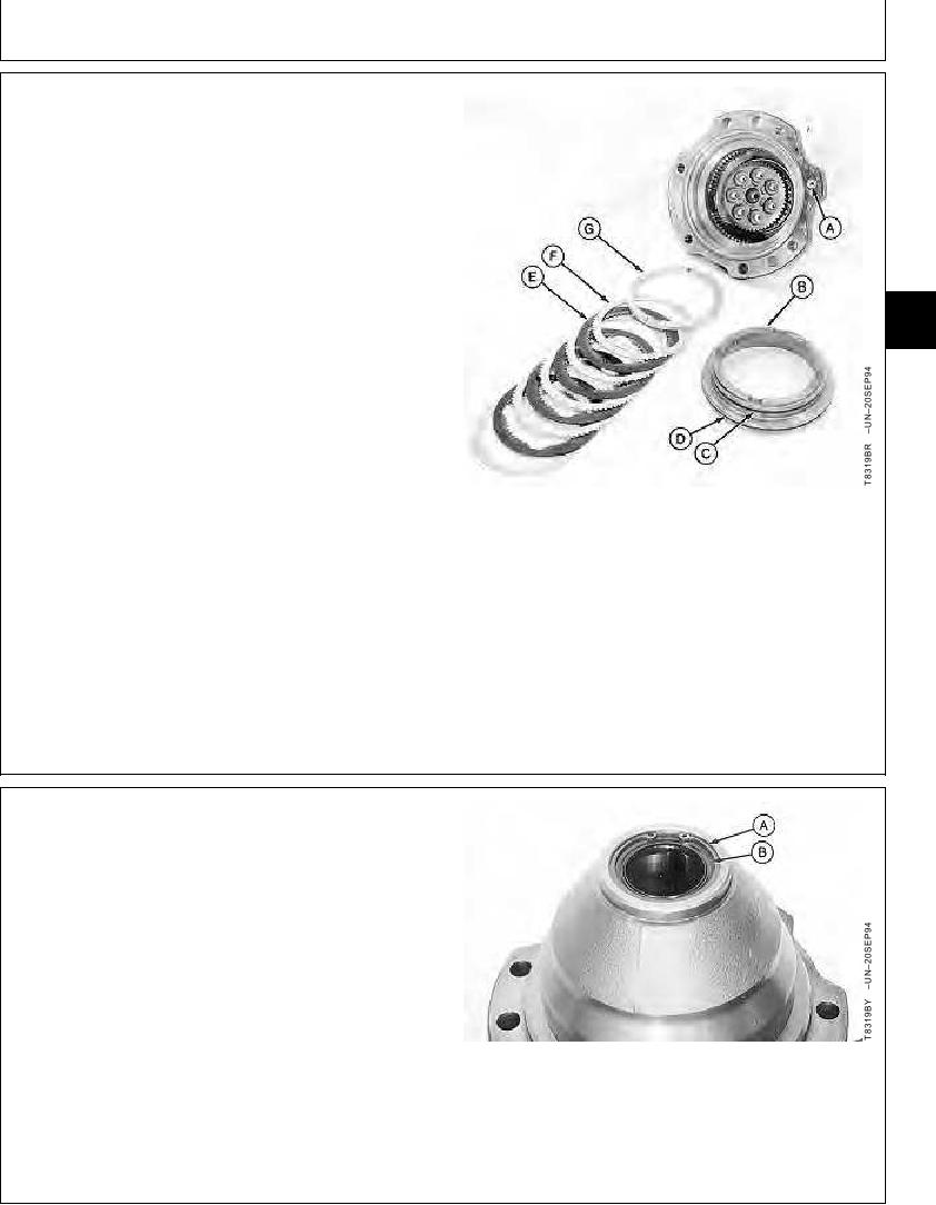
NOTE: Remove piston evenly from bore. Do not scratch
or damage piston or bore.
6. Make sure brake port (A) is clear to allow air to enter
as piston (B) is removed from bore.
7. Remove brake parts (B--G).
NOTE: If parts are not within specification, replace parts.
8. Inspect brake parts for wear or damage.
02
0260
9
Disk Spring--Specification
Height .......................................................... 6.4--6.5 mm (0.25--0.26 in.)
Disk--Specification
Thickness............................................. 3.25--3.30 mm (0.128--0.130 in.)
Plate--Specification
Thickness............................................. 1.75--1.80 mm (0.069--0.071 in.)
A--Brake Port
B--Piston
C--O-Ring
D--O-Ring
E--Disk (4 used)
F--Plate (5 used)
G--Spacer
CED,OUOE023,172
1929MAY986/12
9. Turn motor shaft and brake housing over. Hit end of
drive shaft with a soft-faced hammer to remove motor
drive shaft assembly from housing.
10. Remove snap ring (A) and lip seal (B).
A--Snap Ring
B--Lip Seal
Continued on next page
CED,OUOE023,172
1929MAY987/12
10-48

