
TM 5-3805-281-24-2
Batteries, Support, and Cables
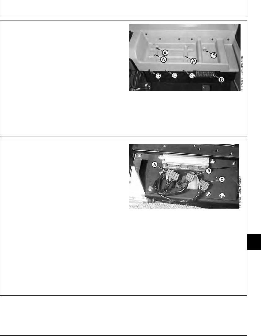
2. Remove cap screws (A and C) and the fuse box cover
(B) to remove the rear console cover.
A--Cap Screw (4 used)
B--Fuse Box Cover
C--Cap Screw (3 used)
TX,16,UU3295 1905JUN922/3
3. Loosen EPC connectors and remove connectors (A--
C).
4. Turn charger off before connecting or disconnecting it.
5. Charge battery following manufacturer's instructions for
your battery charger.
6. After battery is charged, connect the positive (+) cable,
then connect the negative (-) ground cable.
7. Push connectors into EPC controller.
A--EPC Connector
8. Install rear console cover and fuse box cover
B--EPC Connector
C--EPC Connector
9. After connecting batteries, engine speeds must be
recalibrated:
16
1671
11
TX,16,UU3295 1905JUN923/3
15-11

