
TM 5-2420-230-24-2
B3.9 and B5.9 Series Engines
Engine Diagrams
Section E - Engine Identification
Page E-27
Engine Diagrams
Engine Views
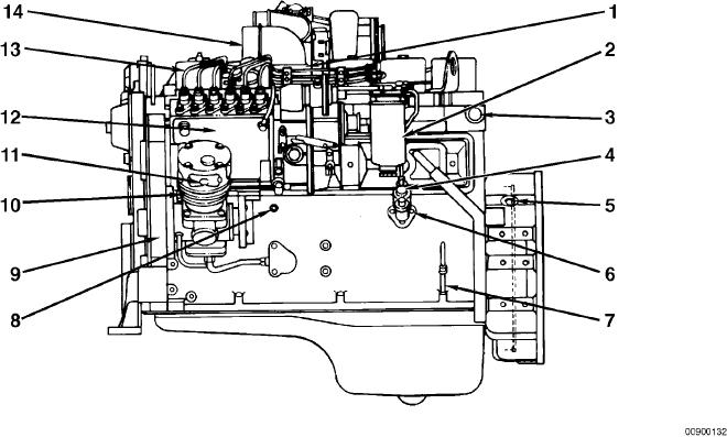
The following illustrations show the locations of the major external engine components, filters, and other service and
maintenance points. Some external components will be at different locations for different engine models.
NOTE: The illustrations are only a reference to show a typical engine.
Fuel Pump Side View
8. 1/8-inch NPTF oil pressure
1. Intake air heater (if equipped)
9. Engine dataplate
2. Fuel filter and water separator
10. Air compressor
3. 3/4-inch NPTF water heater
11. Air compressor air intake
4. 1/4-inch NPTF fuel inlet connection
12. In-line fuel injection pump
5. 3/4-16 UNF magnetic pickup location
13. High-pressure fuel lines
6. Fuel lift pump
14. Engine air inlet.
7. Oil dipstick
L-579