
TM 5-2420-230-24-2
Camshaft (001-008)
B3.9 and B5.9 Series Engines
Page 1-20
Section 1 - Cylinder Block - Group 01
Operate the engine at idle for 5 to 10 minutes. Check for
loose parts and leaks.
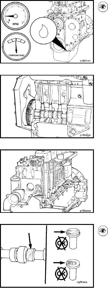
Camshaft (001-008)
General Information
The camshaft is gear-driven from the crankshaft. A re-
placeable bushing is used for the front journal to carry the
side-loading from the accessory drive. The remainder of
the journals operate in cast-iron bores in the cylinder block;
however, these bores can be repaired in a machine shop
by installing service bushings.
The camshaft has lobes to operate the intake and exhaust
valves and a special lobe to drive the fuel transfer pump.
The valve lobes contact "mushroom"-shaped valve tappets
that operate the push tubes. The operating arm of the fuel
transfer pump rides directly on the special lobe on the
camshaft. The profile of the camshaft lobes is the same for
all B Series engines except 1994 automotive engines, which
use a new early intake valve opening intake lobe.
Diagonosing Malfunctions
Loose rocker levers and the need to reset the valve clear-
ance fequently can indicate camshaft lobe or tappet wear.
If an inspection of the levers, valve stems, and push tubes
does not show wear, then tappet or camshaft lobe wear
should be suspected.
L-698