
TM 5-2420-230-24-2
Cooling System - Air or Combustion Gas Test (008-019)
B3.9 and B5.9 Series Engines
Page 8-20
Section 8 - Cooling System - Group 08
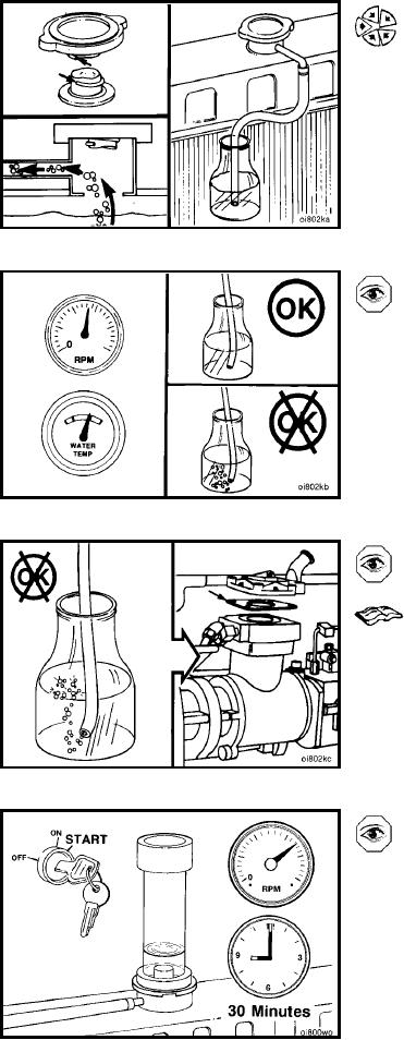
NOTE: The pressure cap must make a tight seal.
Install a radiator pressure cap that has had the spring and
pressure relief valve removed.
Attach a rubber hose to the radiator overflow connection.
Place the free end of the hose in a container of water.
Operate the engine at rated rpm until it reaches a tem-
perature of 80C [176F] with the thermostat open.
Check for a continuous flow of air bubbles from the hose
in the water container.
A continuous flow of air bubbles can be caused by one of
the following:
Fan, shutter, or heater air control thermostat valve
leaking air.
An air compressor cylinder head leak. Refer to Pro-
cedure 012-019 for air compressor leak test.
If one of the air control valves or the air compressor was not
the source of air entering the cooling system, perform the
Combustion Gas Leak test.
L-1076