
TM 5-2420-230-24-2
B3.9 and B5.9 Series Engines
Air Intake Manifold Heater (010-072)
Section 10 - Air Intake System - Group 10
Page 10-65
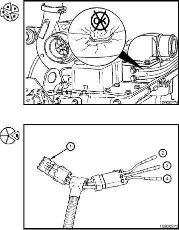
NOTE: The wiring harness should be secured within 152
mm [6 in] of any connection to avoid connector or ring
terminal damage.
Install the wiring harness, and secure to avoid chafing or
burning.
If the engine does not have an electrical shutdown sole-
noid or it has a timer module for the shutdown solenoid, use
the 3-pin connector tee to wire the vehicle as illustrated.
Refer to the table below.
Connector Let-
Function
Recommended Location
ter
A
Module Power
Keyswitch ON power sup-
ply
B
Crank Sensor
``S'' Terminal on starter or
keyswitch ``Crank''
C
Ground (-)
Engine, Chassis, or Bat-
tery Ground (-)
L-1189