
TM 5-2420-230-24-2
A/C Cylinder Head (QE Models) (012-104)
B3.9 and B5.9 Series Engines
Page 12-44
Section 12 - Compressed Air System - Group 12
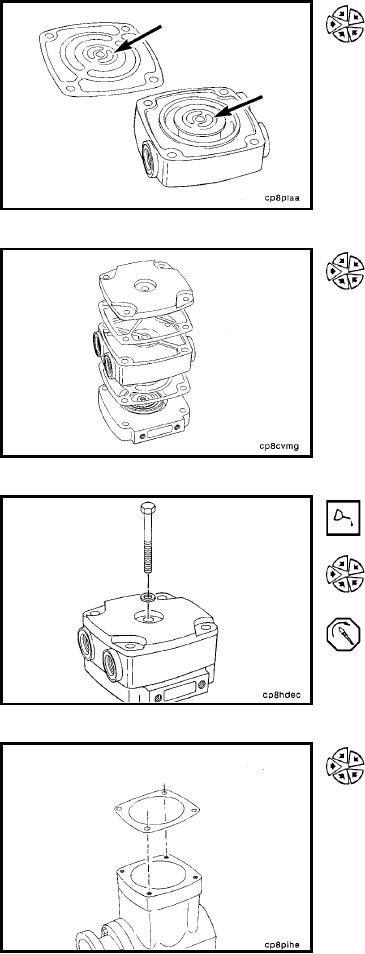
Determine the final orientation of the valve plate (air intake
location) and the head (coolant ports in relation to air inlet
or manifold location). Align the kidney-shaped slots in the
head with the kidney-shaped slots in the gasket.
If orientation marks were made before disassembly, use
them.
Assemble the cover, cover gasket, head, head gasket, and
valve plate.
NOTE: Make sure corner capscrew holes are aligned.
Lubricate the threads under the head.
Install the shorter capscrew with washer through the center
hole.
Torque Value: 14 Nm
[124 in-lb]
Install the valve plate gasket.
L-1248