
TM 5-2420-232-10
0003
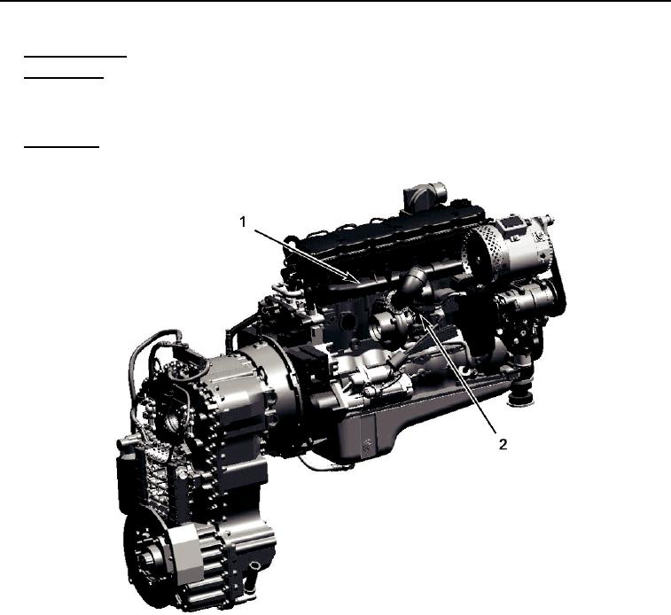
EXHAUST SYSTEM
0003
1.
Exhaust Manifold (1) - collects exhaust gas from each cylinder of the engine and directs it to the turbocharger.
2.
Turbocharger (2) - is an exhaust gas-driven twin turbine device to increase the amount and pressure of the air entering
the intake manifold and the engine. Each turbine is secured to a central shaft and is contained in its own housing. As the
exhaust gas passes over the exhaust turbine, it turns the shaft, thus turning the intake turbine (compressor) which forces air
into the intake manifold. The effect is to increase the engine horsepower.
Exhaust Pipe - directs exhaust gases from the engine compartment.
3.
435-A0229
Figure 4. Exhaust System
03
FUEL SYSTEM
0003
A low pressure fuel pump draws fuel from the tank through an on/off tap and a pre-filter/water separator. The fuel is then
pumped through a fine fuel filter to the high pressure pump which supplies fuel to the injectors, which are individually con-
trolled electronically.
0003-5