
TM 5-2420-232-10
0004
HVAC CONTINUED
Supplementary Defrost System
0004
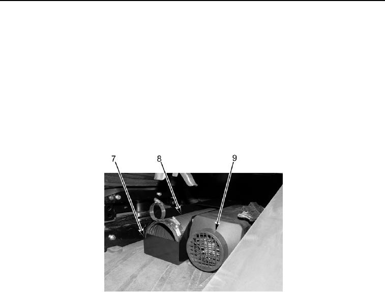
To assist the defrosting of the front windshield, the machine is equipped with a supplementary defrost system, which consists
of a hose (Figure 92, Item 8) and three clamps that are stowed in a box (Figure 92, Item 7) that is secured to the side of the sup-
plemental cab heater unit (Figure 92, Item 9) beneath the passenger seat.
1. When required, remove the hose (Figure 92, Item 8) from the box (Figure 92, Item 7).
2.
Secure one end of the hose (Figure 93, Item 8) to the heater unit (Figure 93, Item 9) with one large clamp
(Figure 93, Item 13).
3.
Secure the other end of the hose (Figure 93, Item 8) to the rifle rack (Figure 93, Item 11) with the other large clamp
(Figure 93, Item 12) around the hose and the small clamp (Figure 93, Item 10) attached to the rifle rack.
4.
Using the supplementary cab heater control knob (Figure 91, Item 6), the operator then directs the open end of the hose
(Figure 93, Item 8) across the windshield.
435-A1756
Figure 92. Supplementary Defrost System Stowage
04
Change 1
0004-94