
TM 5-2420-232-10
0042
BACKHOE CONTROLS CONTINUED
Auger Attachment
00042
1.
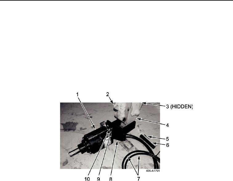
Attach auger (Figure 8, Item 1) to bracket (Figure 8, Item 8) with pin (Figure 8, Item 9) and two clips (Figure 8, Item 10).
2.
Position auger (Figure 8, Item 1) facing away from machine with two hoses (Figure 8, Item 7) facing down.
3.
Level bracket (Figure 8, Item 8) with blocks.
4.
Place bucket link (Figure 8, Item 2) in fully retracted position.
5.
Position dipper arm (Figure 8, Item 4) in bracket (Figure 8, Item 8)
6.
Attach bracket (Figure 8, Item 8) to dipper arm (Figure 8, Item 4) with pin (Figure 8, Item 6) and two cotter pins (Figure
8, Item 5).
7.
Connect two hoses (Figure 8, Item 7) to auxiliary quick disconnect fittings (Figure 8, Item 3) on dipper arm (Figure 8,
Item 4).
Figure 8. Auger Attachment
042
0042-10