
TM 5-3805-280-24-1
System Information
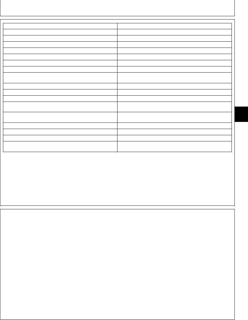
Step 3--Switch OFF
Check component side of circuit breaker for continuity to ground
Continuity to ground. Repair grounded circuit at or before switch.
No continuity to ground, replace circuit breaker.
Step 4--Switch ON
Check component side of circuit breaker for battery voltage
Battery voltage normal. Go to Step 6.
Low voltage, repair high resistance.
No voltage. Go to Step 5.
Step 5
Disconnect wire at battery side of component (G). Switch ON. Check
Battery voltage, repair component.
wire at (G) for battery voltage
No voltage, repair grounded or open circuit at or after switch.
Step 6--Switch ON
Check lead to component at (G) for battery voltage
Battery voltage normal. Go to Step 7.
Low voltage, repair high resistance in circuit between fuse and
9015
component.
05
No voltage, repair high resistance or open circuit between fuse and
17
component.
Step 7--Switch ON
Check ground wire of component at (I) for voltage
No voltage, good continuity to ground.
Repair component.
Voltage, poor continuity to ground. Repair high resistance or open
ground circuit.
TX,9015,MM2917B 1901MAY952/2
SYSTEM FUNCTIONAL SCHEMATIC INFORMATION
letter/number designation, (S1 Key Switch, F21 Battery
SYSTEM FUNCTIONAL SCHEMATIC DIAGRAM
Power 40 Amp Fusible Link, etc.) will indicate that
component throughout the manual. The System
The System Functional Schematic is a schematic
Functional Schematic is divided into Sections. Each
diagram of the complete machine. All harnesses are
section contains one or more electrical circuits. Each
identified by letter/number designation and
section is indicated by a number and circuit (SE1
description--Engine and Frame Harness (W1), Cab
Power Circuit, SE2 Starting Circuit, etc.)
Harness (W2) etc. Each wire is identified by color (Blk,
Red/Wht, Blk/Wht etc.) All components are identified
NOTE: All System Functional Schematic Diagrams are
by letter/number designation, description and are
shown with key switch in the off position.
represented by a schematic symbol. Component
CED,OUTX782,6 1919NOV981/1
4-16