
TM 5-3805-280-24-1
Sub-System Diagnostics
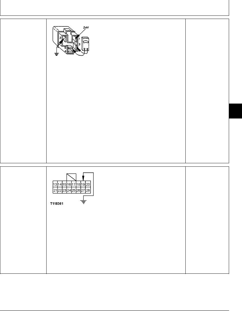
WORK LIGHT RELAY
1--24-Volt Terminal
YES: Relay is OK.
(K3) CHECK
2--Ground Terminal
3--Relay Common
NO: Relay has failed.
4--Relay Normally Closed
Replace.
5--Relay Normally Open
Disconnect harness from relay.
Connect ohmmeter to terminals 3 and 5.
T7447BG
1914JAN91
Does ohmmeter read open?
Connect 24 volts to relay terminal 1 and ground terminal
2.
Does relay 'click'?
With 24 volts still connected to terminal 1, connect
ohmmeter to terminals 3 and 5.
9015
15
Does ohmmeter read continuity?
35
1/1
YES: Light switch on
DRIVE LIGHTS (E2, E7,
monitor controller and
E8) CIRCUIT CHECK
display panel has failed.
Replace.
NO: Check light bulbs,
wire harness and drive
light relay.
T118361 UN21NOV98
Disconnect 16-pin harness connector from monitor controller and display panel.
Ground harness connector pin 19.
Do drive light E2 and left and right cab lights E7 and E8 operate with key switch in
ACC position?
1/1
4-100