
TM 5-3805-280-24-1
Theory of Operation
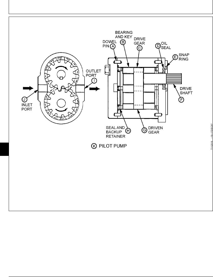
PILOT PUMP OPERATION
9025
05
2
port (I) is connected to the pilot pressure regulating
The pilot pump (K) is a fixed-displacement, external
valve and pilot filter. The outlet is also connected by a
gear pump. The pilot pump is attached to the pump
tube and passages in pump housing to the small end
drive gearbox just to the rear of the rear pump. The
of the front and rear pump servo piston and the pump
pump is driven through a gear train by the rear pump.
regulators.
The inlet port (J) is connected by a suction line to the
suction line for the front and rear pumps. The outlet
TX,9025,GG2283
1922APR981/1
6-2