
TM 5-3805-280-24-1
Theory of Operation
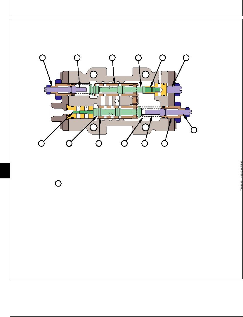
HYDRAULIC PUMP REGULATOR COMPONENT OPERATION
FLOW ADJUSTING
REMOTE
MAXIMUM FLOW REMOTE
CARTRIDGE
MINIMUM FLOW
CONTROL
CONTROL
(TRACK CYCLE
ADJUSTING
ADJUSTING
PISTON
SPOOL
SLEEVE
TIME)
SCREW
SCREW
A
B
C
D
E
F
G LOAD
ADJUSTING
SCREW
(INNER SPRING)
M
L
K
J
I
H
(ENGINE
OUTER INNER LOAD
LOAD
LOAD
LOAD
PULLDOWN AT
SPRING SPRING ADJUSTING
SLEEVE
PISTON
SPOOL
HIGH PRESSURE)
CARTRIDGE
(OUTER SPRING)
9025
(ENGINE
05
PULLDOWN AT
18
MEDIUM PRESSURE)
N PUMP REGULATOR COMPONENTS
T101949
sleeve (K), load spool (L), and load piston (M). Each
The pump regulators are mounted on the top of the
regulator controls the flow of pilot oil to the large end
hydraulic pump housing. The major pump regulator
of its servo piston using the spools and sleeves.
components (N) are the flow adjusting cartridge (A),
maximum flow (displacement) adjusting screw (B),
The remote control spool (D) is moved by a reduced
remote control sleeve (C), remote control spool (D),
pilot oil control signal from front and rear pump control
piston (E), minimum flow (displacement) adjusting
valve. There is a pump control valve located in the left
screw (F), load adjusting screw (inner spring) (engine
and right control valves. The control signal acts on the
pull down at high pressure) (G), load adjusting
end of the piston (E) to control the position of remote
cartridge (outer spring) (engine pull down at medium
control spool against the spring.
pressure) (H), inner spring (I), outer spring (J), load
Continued on next page
TX,05,GG2148 1919MAY981/2
6-17