
TM 5-3805-280-24-1
Theory of Operation
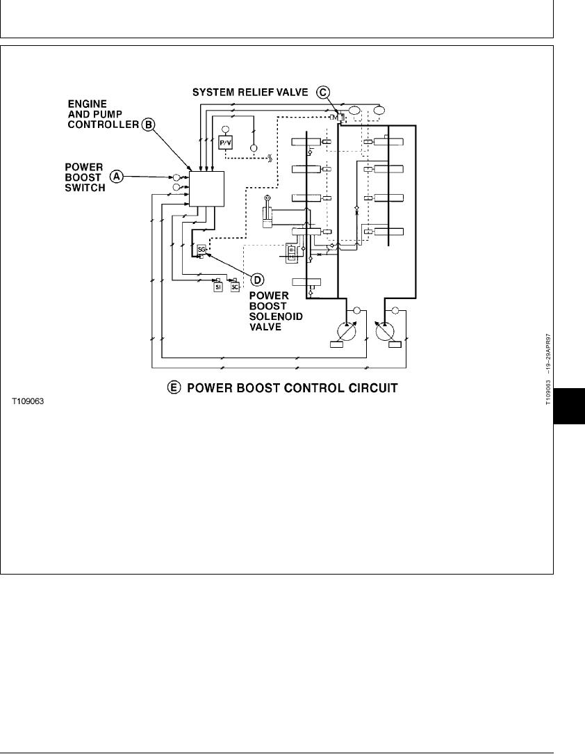
POWER BOOST CONTROL CIRCUIT OPERATION
9025
05
43
energize the power boost solenoid valve (D) coil. The
The function of power boost control circuit (E) is to
pilot oil pressure signal pushes the piston in the
temporarily increase the main hydraulic system
system relief valve (C) down increasing the pressure
operating pressure by increasing the system relief
setting. The main hydraulic system can now operate at
valve pressure.
a higher operating pressure for approximately 8
seconds.
When the power boost switch (A) is pushed the engine
and pump controller (B) sends an electrical signal to
TX,05,GG2202
1929MAY981/1
6-41