
TM 5-3805-280-24-1
Theory of Operation
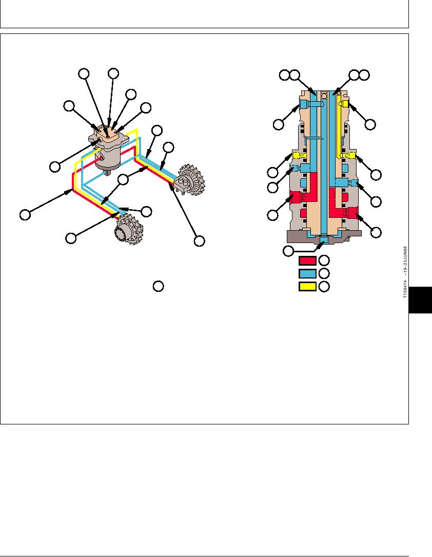
ROTARY MANIFOLD OPERATION
D RIGHT PROPEL
LEFT PROPEL C
B C
E D
REVERSE
FORWARD
F PROPEL SPEED CHANGE
LEFT B
E RIGHT PROPEL
PROPEL
FORWARD
REVERSE
A
F
A RIGHT PROPEL DRAIN
D RIGHT PROPEL REVERSE
DRAIN A
F
F
F PROPEL
B
SPEED
CHANGE
D
A LEFT
C LEFT PROPEL
C
PROPEL
FORWARD
DRAIN
E
B LEFT
E RIGHT
PROPEL
PROPEL
A
REVERSE
FORWARD
G SUPPLY OIL
H RETURN OIL
J ROTARY MANIFOLD
I PILOT OIL
T109474
9025
05
71
The rotary manifold (J) is a 360 rotary joint. It allows
Oil flows into and through the spindle to passages in
the housing, and then out of the housing to the propel
oil to flow to and from the propel motors without
motors. Sealing rings stop oil from leaking between the
twisting hoses when the upperstructure is rotated.
spindle and housing into adjacent passages.
The inner spindle is connected to the upperstructure
and the housing is connected to the undercarriage.
The housing rotates about the spindle during swing
operation.
TX,05,GG2171
1920MAY981/1
6-67