
TM 5-3805-280-24-1
Tests
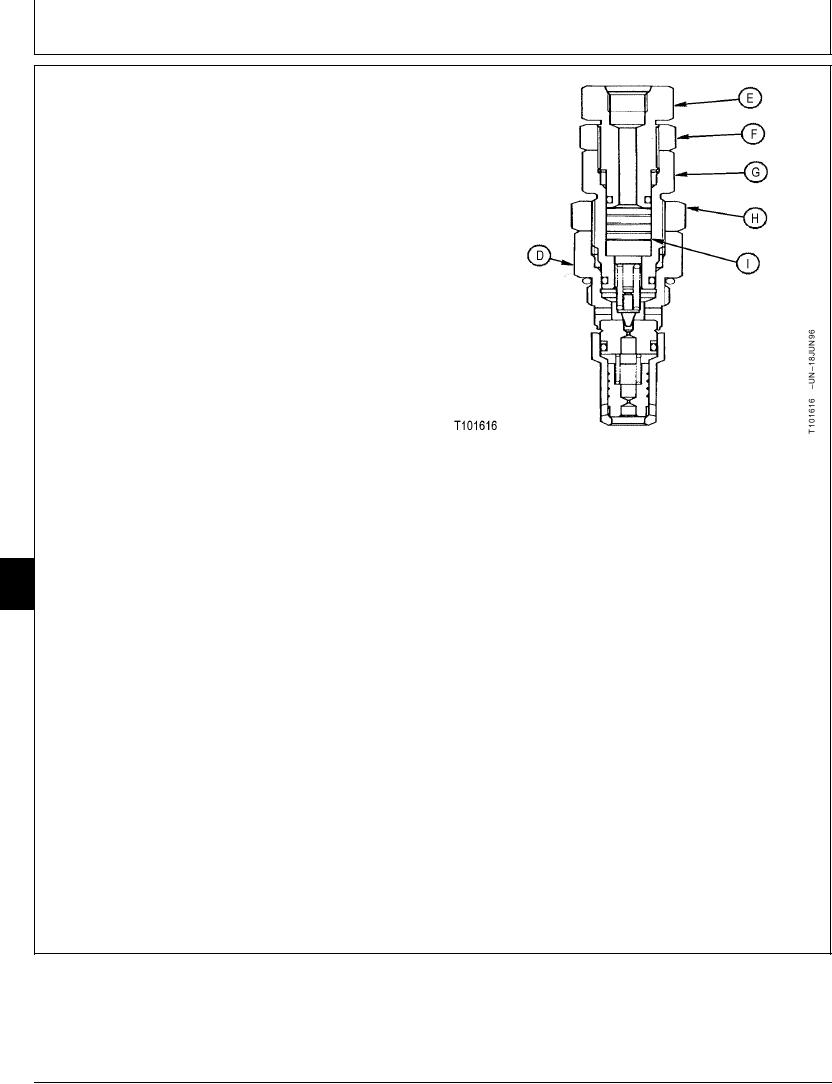
9. Disconnect pilot line from elbow in system relief valve
(D) so adjustment can be made without twisting power
boost pilot line. Connect pilot line before starting
engine and applying pressure.
10. Loosen 27 mm nut (F).
11. Turn first adjusting plug (E) in until piston (I) is
against bottom of bore in second adjusting plug (G).
Tighten nut. Connect pilot line.
12. Loosen 32 mm nut (H).
13. Start engine. Actuate the arm in function over relief.
14. Turn second adjusting plug in to increase pressure;
turn adjusting plug out to decrease pressure to get
specified pressure for power boost.
Hold adjusting plug and tighten 32 mm nut.
D--System Relief Valve
32 mm Nut--Specification
E--First Adjusting Plug
F--27 mm Nut
Torque .............................................................. 78--88 Nm (58--65 lb-ft)
G--Second Adjusting Plug
H--32 mm Nut
15. Loosen 27 mm nut (F).
I--Piston
16. Actuate the arm in function over relief.
9025
25
70
17. Turn first adjusting plug (E) out to decrease pressure
to get specified pressure for system relief valve.
Hold adjusting plug and tighten 27 mm nut.
27 mm Nut--Specification
Torque .............................................................. 59--68 Nm (43--51 lb-ft)
18. Check the pressures again.
TX,9025,GG2648 1908JUN985/5
6-201