
TM 5-3805-280-24-1
Tests
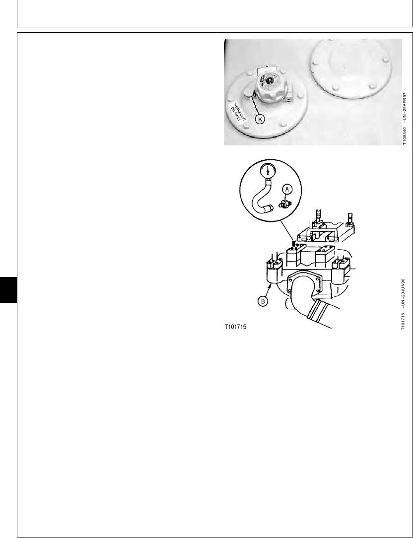
If laptop computer is not available, use the digital
pressure and temperature analyzer, and transducer, or
a gauge.
a. Stop the engine.
b. Loosen vent plug (K) to release the air pressure in
hydraulic oil tank.
c. Install adapter (A) and male quick coupler to test
port on rear pump (B). Connect the analyzer and
transducers or gauges.
2. Install the temperature probe on the hydraulic
tank-to-pump suction line. (See JT05800 Digital
Thermometer Installation in this group.)
3. Heat hydraulic oil to the specified temperature. (See
Hydraulic System Warm-Up Procedure in this group.)
Oil--Specification
Temperature ........................................................... 50 5C (120 10F)
4. Raise and lower boom to pressurize hydraulic tank.
5. Run machine at specifications.
9025
25
Engine in Standard Mode--Specification
78
Speed ........................................................................................... Slow Idle
Work Mode Selector--Specification
Position ........................................................................................ Dig Mode
A--Adapter
E Mode Switch--Specification
B--Rear Pump
K--Vent Plug
Position .................................................................................................. Off
HP Mode Switch--Specification
Position .................................................................................................. Off
Auto-Idle Switch--Specification
Position .................................................................................................. Off
6. Operate the swing function at stall. To stall swing
function, put bucket against an immovable object or in
a trench then actuate the control lever to full stroke.
Continued on next page
TX,9025,GG2650
1928APR973/5
6-209