TM 5-3805-281-24-1
Theory of Operation
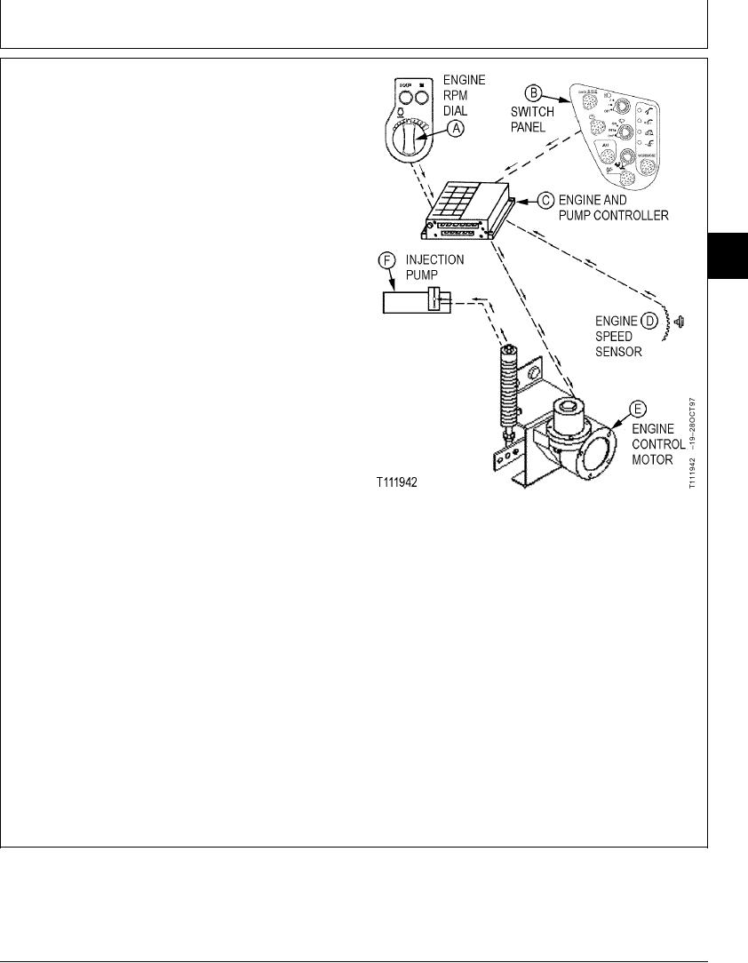
The engine speed control components allows the operator
to choose engine speeds to match operating conditions
and to operate the engine as efficiently as possible.
Engine speeds from slow idle to fast idle in standard
mode are selected by the engine rpm dial (A) located in
the right console panel in cab. The E (economy) mode
and HP (high power) mode are selected by switches
located in the right console panel just above the engine
rpm dial. The auto idle mode is selected by a switch
located in the switch panel (B). Indicators in the monitor
9010
05
panel are lit to indicate when the E mode, HP mode, and
5
auto-idle mode switches are pushed to activate the
function.
AI=Auto Idle Mode Switch
E=Economy Mode Switch
HP=High Power Mode Switch
Turning the engine rpm dial or pushing the AI, E, or HP
mode switches sends an electrical signal to the controller.
The engine and pump controller (C) senses the signal and
sends an electrical signal to the engine control motor (E).
The engine control motor regulates engine speed through
a push-pull cable attached to the fuel injection pump (F)
lever. The engine and pump controller is located under
the console cover behind the seat. The engine control
motor is located in the hydraulic pump compartment.
The engine speed sensor (D) (located in the pump drive
gearbox adjacent to the front pump) counts the pump
drive gear teeth as the gears rotate. This senses actual
engine speed. The sensing signal is sent to the engine
and pump controller which calculates engine speed.
CED,TX08227,3178
1906JUN982/2
3-5

