
TM 5-3805-281-24-1
Sub-System Diagnostics
PROPEL AUTO IDLE
YES: Wire are OK. Go to
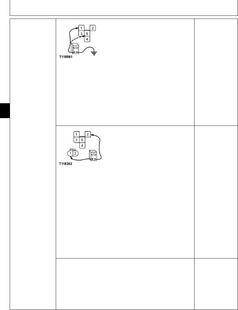
RELAY (K10) HARNESS
next step.
CHECK
NO: Wire has failed.
Repair.
T118561 UN21NOV98
Turn key switch OFF.
Remove harness connector from relay
With ohmmeter measure continuity from relay harness connector pin 5 to ground.
Is continuity measured?
9015
15
Turn key switch to ON and measure voltage at pin 1.
90
Is 24 volts measured?
YES: Wire and isolation
diode V4 are OK. Go to
next step.
NO: Check wire for open.
If OK, go to diode V4
check.
T118362 UN21NOV98
1--24-Volt Pin
2--Ground Pin
3--Relay Common
4--Relay Normally Closed
5--Relay Normally Open
Turn key switch OFF.
Disconnect wiring harness at propel pressure switch.
NOTE: Use "diode checking mode" on meter when checking this reading.
pin 1.
Measure resistance, then reverse ohmmeter probes and measure resistance again.
Does resistance read approximately 500 ohms in one direction, and open in the other
direction?
1/2
4-158