TM 5-3805-281-24-1
Theory of Operation
TO PROPEL SPEED
CHANGE VALVE I
H TO SYSTEM
RELIEF VALVE
TO PUMP REGULATORS K
SPEED SENSING PORT
TO ARM
REGENERATIVE L
VALVE
J TO HYDRAULIC
OIL TANK
SOLENOID A
VALVE
MANIFOLD
P FROM PILOT
SHUT-OFF VALVE
Q TO SWING PARK BRAKE
RELEASE VALVE PG PORT
R FROM ARM HEAD END REDUCED
LEAKAGE VALVE DR PORT
S TO REAR PUMP CONTROL
VALVE IN LEFT CONTROL VALVE
T FROM BUCKET FLOW
9025
FROM PILOT B
CONTROL PILOT VALVE A
C
05
SHUT-OFF VALVE
26
U FROM BUCKET FLOW
FROM ARM
REGENERATIVE
CONTROL PILOT VALVE B
VALVE
V TO FRONT PUMP CONTROL
VALVE IN RIGHT CONTROL VALVE
T115178
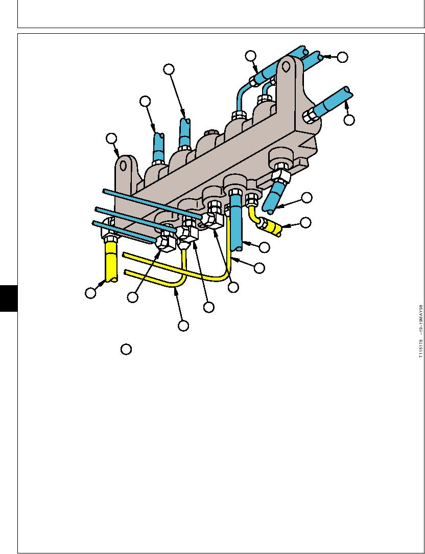
W SOLENOID VALVE MANIFOLD -- BOTTOM
bucket flow control pilot valve B (U) flows through the
The solenoid valve manifold (O and W) is mounted on
manifold to the hydraulic oil tank (J). Also the spool
the control valve mounting bracket at the front of the
end of bucket flow control pilot valve B is open to the
control valve. The manifold serves as the central
manifold through bucket flow control pilot valve A (T)
distribution point for pilot oil (M) to the arm
when arm-in function is not actuated. (See Bucket
regenerative (D), speed sensing (E), propel speed
Flow Control Valve Operation in this group.)
change (F), and power boost (G) solenoid valves, the
front (V) and rear (S) pump control valves, and the
When the solenoid valve coils are de-engerizes, the
swing park brake release valve (Q). Pilot oil flows to
valves are open to return through the manifold to the
the manifold from the pilot shut-off valve (B) when the
hydraulic oil tank. When a solenoid valve coil is
lever is pushed forward to the unlock position.
energized, the path to return is blocked and a path is
opened for pilot oil to flow through the solenoid valve
Return oil (N) from the spring end of arm regenerative
to the function. (See Proportional Solenoid Valve
valve (C), pilot shut-off valve (P), arm head end
Operation in this group.)
reduced leakage valve DR port (R), and spring end of
Continued on next page
CED,TX08227,3115
1901MAY982/3
6-26

