
TM 5-3805-281-24-1
Diagnostic Information
NOTE: Do not use manufacturer's identification tags or
markings on line ends to identify lines for this
conversion procedure. The conversion must be
done on the side of flow regulator valve that is
connected to the pilot controllers.
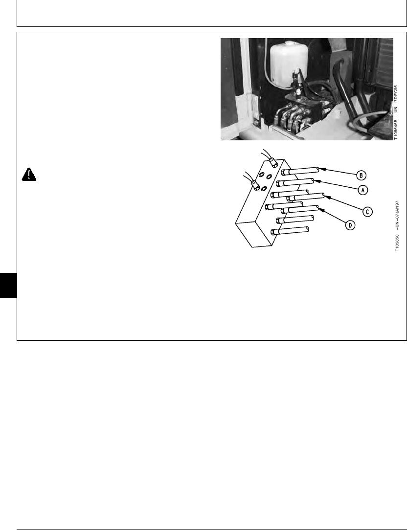
7. Switch the hoses (A--D) from pilot controllers at the
front right side (the side towards oil cooler) of flow
regulator valve. Hoses are switched in a X pattern.
Switch hose (A) with hose (C).
Switch hose (B) with hose (D).
CAUTION: Prevent injury from unexpected
control lever function. Install new decals on
control consoles.
8. Install new decals (black on yellow) on control
consoles near the base of control levers. Decals are
enclosed in Operator's Manual package. Additional
decals are available through parts.
9025
15
24
TX,9025,GG2511 1911FEB972/2
6-131