
TM 5-3805-281-24-1
Tests
If laptop computer is not available, use the digital
pressure and temperature analyzer, and transducers or
gauges.
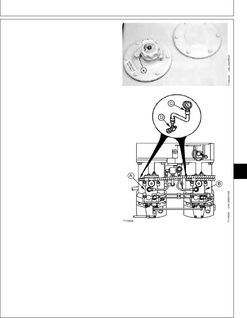
a. Stop the engine.
b. Loosen vent plug (K) to release the air pressure in
hydraulic oil tank.
c. Install tees (C) and male quick couplers in line with
rear and front pump control valve pilot lines at rear
(A) and front (B) pump regulators. Connect the
analyzer and transducers or gauges (D).
3. Heat hydraulic oil to the specified temperature. (See
Hydraulic System Warm-Up Procedure in this group.)
Hydraulic Oil--Specification
Temperature ........................................................... 50 5C (120 10F)
4. Run the machine at specification.
Engine--Specification
Speed .................................................................... Slow Idle and Fast Idle
Work Mode Selector--Specification
9025
25
Position ........................................................................................ Dig Mode
99
E Mode Switch--Specification
Position .................................................................................................. Off
HP Mode Switch--Specification
Position .................................................................................................. Off
Auto-Idle Switch--Specification
Position .................................................................................................. Off
A--Rear Pump Regulator
B--Front Pump Regulator
a. Run engine at slow to fast idle with all functions in
C--JT03001 Tee
neutral. Record pressure reading for front and rear
D--7 000 kPa (70 bar) (1 000 psi) Gauge
pump control valves.
K--Vent Plug
b. Raise left track off the ground to check rear pump
or right track for front pump. Run engine at fast idle.
Operate the raised track at full speed. Record
pressure readings.
Continued on next page
CED,TX08227,3139
1927MAY983/4
6-246