
TM 5-3805-281-24-2
Hydraulic System
NOTE: Do not use manufacturer's identification tags or
markings on line ends to identify lines for this
33
conversion procedure. The conversion must be
3360
done on the side of flow regulator valve that is
16
connected to the pilot controllers (toward front of
cab).
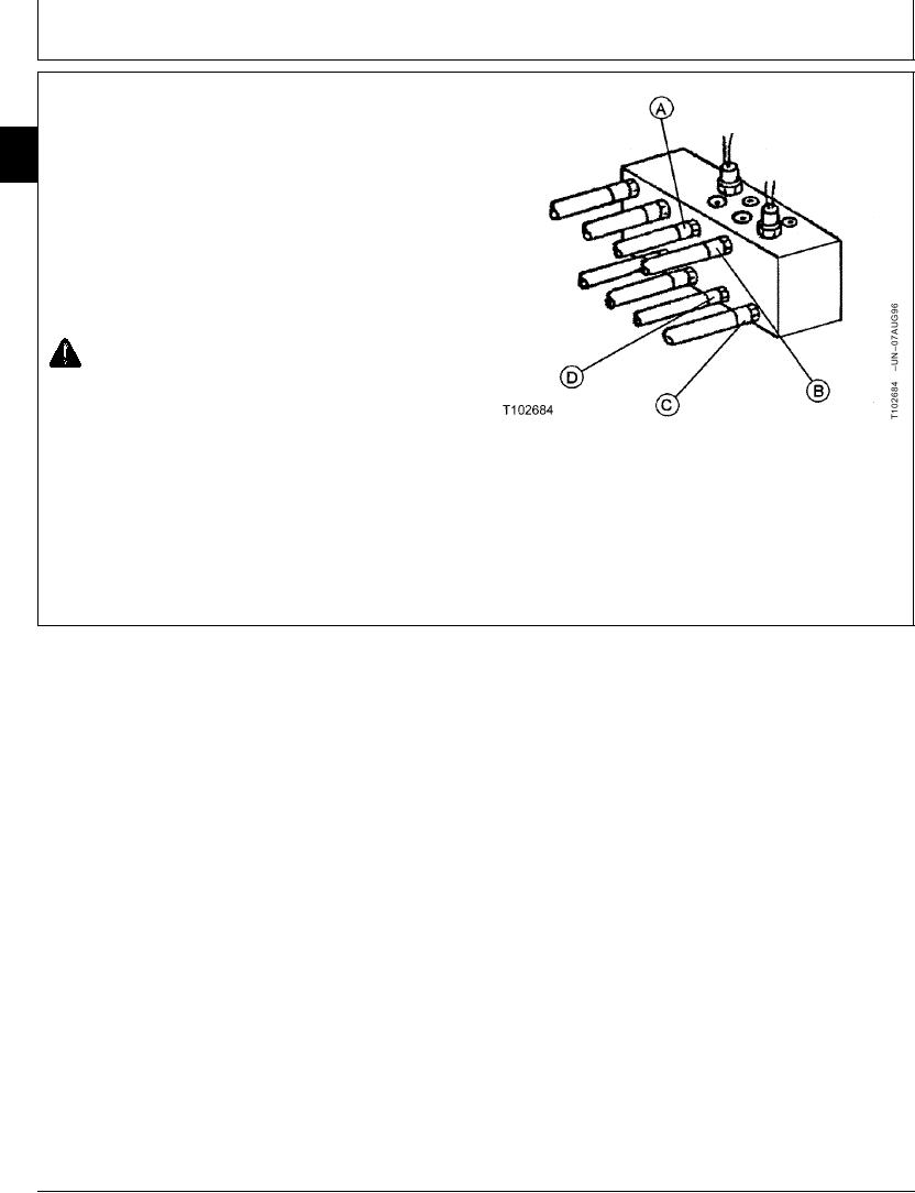
8. Hoses are switched in an X pattern.
Switch hose (A) with hose (C).
Switch hose (B) with hose (D).
CAUTION: Prevent injury from unexpected
control lever function. Install new decals on
control consoles.
9. Install new decals (black on yellow) on control
consoles near base of control levers. Decals are
A--Hose
enclosed in Operator Manual package. Additional
B--Hose
decals can be purchased from your John Deere dealer.
C--Hose
D--Hose
CED,OUOE027,290
1902JUN983/3
19-53