
TM 5-3805-281-24-2
Mechanical Drive Elements
CAUTION: To avoid injury from escaping fluid
under pressure, stop engine and relieve the
pressure in the system before disconnecting
hydraulic or other lines. Tighten all connections
before applying pressure.
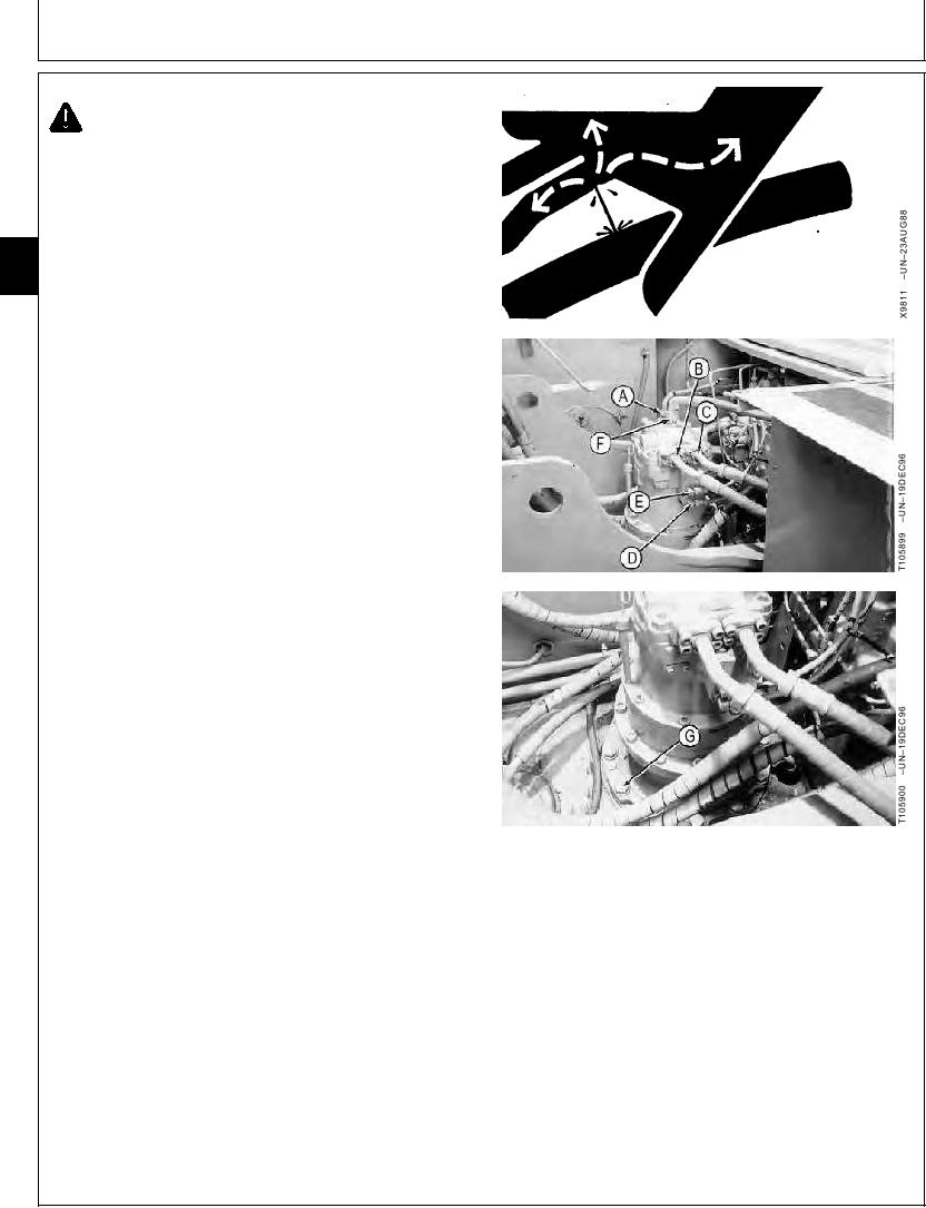
3. Disconnect lines (A--F).
43
4350
4. Remove cap screws (G).
6
A--Swing Motor Top Right Port-to-Reservoir
Return Line
B--Swing Motor Left Front "B" Port-to-Main
Control Valve Left Rear Lower Port Line
C--Swing Motor Left Rear "A" Port-to-Main
Control Valve Left Rear Upper Port Line
D--Swing Brake Relief Valve
"PG"Port-to-Solenoid Valve Manifold Bottom
Port Line
E--Swing Brake Relief Valve "SH" Port-to-System
Relief Manifold Block Front Port Line
F-- Swing Motor Top Left Port-to-Main Control
Valve Left Front Top Port Line
G--Cap Screw (12 used)
Continued on next page
CED,OUOE027,257
1919MAY982/3
21-6