
TM 5-3805-281-24-2
Hydraulic System
43
4360
17
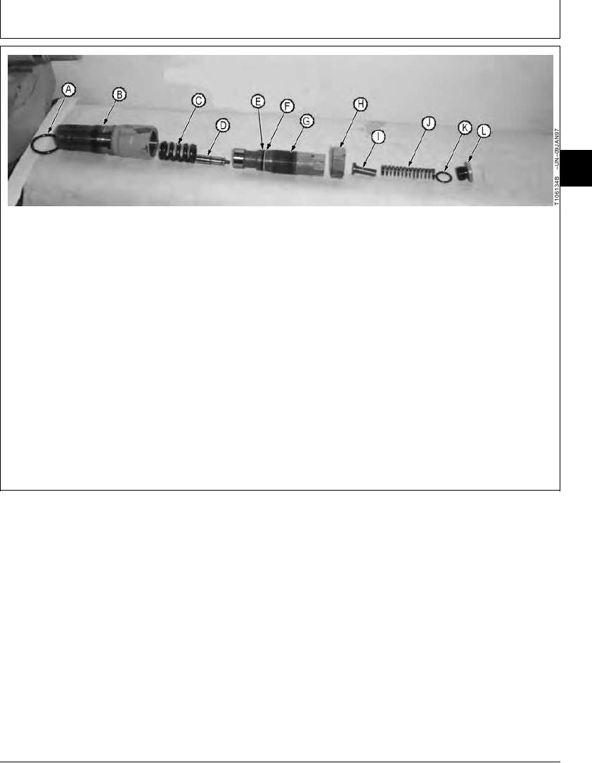
A--O-Ring
D--Piston
G--Adjusting Plug
J--Spring
B--Valve Body
E--O-Ring
H--Nut
K--O-Ring
C--Spring
F--Backup Ring
I--Spring Guide
L--Plug
(G) while assembling. Failure to do
IMPORTANT: Disassembly of relief valve is shown
so will force the plug out the end of
for convenience of cleaning. Service
body.
parts are not available. The relief
valve must be replaced.
10. Assemble relief valve (A--L).
7. Disassemble crossover relief valve (A--L).
11. Adjust plug (G) to original dimension.
8. Clean and inspect parts.
12. Check swing crossover relief valve pressure
setting. (See procedure in Group 9025-25.)
9. Replace relief valve if any part is damaged or worn.
IMPORTANT: Make sure the poppet in body (B)
slides into the bore in adjusting plug
CED,OUOE027,264
1920MAY983/3
21-51