
TM 5-3805-281-24-2
Hydraulic System
0--Propel Pilot Controller
6B--Seal (4 used)
9--Lock Washer (2 used)
15--Cap Screw, Lock
1--Spacer (4 used)
6C--O-Ring (4 used)
10--Cam (2 used)
Washer, and Washer
2--Shim (12 used)
6D--Plunger (4 used)
11--Pin (2 used)
(2 used)
33
3--Balance Spring (4 used)
7--Holder
11A--Bushing (4 used)
16--Plug
3360
4--Spring Guide (4 used)
7B--Bushing (2 used)
12--Spring Pin (2 used)
17--O-Ring
85
5--Return Spring (4 used)
7C--Bushing (2 used)
13--Spring Pin (2 used)
23--Plate
6--Plunger (4 used)
8--Cap Screw (2 used)
14--Cover
30--Housing and Spools
Tighten cap screws (6).
7. Install same number of spacers (1) and shims (2)
on each spool as were removed.
Holder-to-Housing Cap Screw--Specification
Push balance spring (3) down and then install
Torque....................................................................... 49 Nm (36 lb-ft)
spring guide (4) so that concave side is against
spring.
10. Tighten plug (16).
8. Apply grease to oil seals (6B) and O-rings (6C).
Plug-to-Housing--Specification
9. Install parts into housing. Remember to install
Torque....................................................................... 34 Nm (25 lb-ft)
spools into same ports from which they were
removed.
11. Apply grease to the end of plungers (6D).
Slowly push holder down to compress springs and
push parts into housing.
TX,33,GG2558 1911MAR974/4
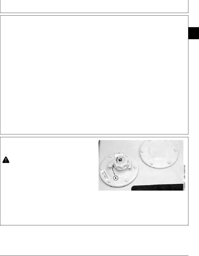
REMOVE AND INSTALL FLOW REGULATOR
VALVE
CAUTION: The hydraulic oil tank is pressurized.
High pressure release of oil from pressurized
system can cause serious burns or penetrating
injury. Release pressure from tank by loosening
vent plug. It is not necessary to remove vent
plug.
1. Loosen vent plug (A) to release air pressure from
hydraulic oil tank.
A--Vent Plug
Continued on next page
CED,OUOE027,269
1928MAY981/2

