8006-23
TM 5-2420-230-24-1
QUICK COUPLER CYLINDER
Disassembly
2. Install the seal (13) and bushing (12) in the gland
(5).
NOTE: Refer to illustrations on page 24.
3. Install the backup ring (15) and O-ring (14) on
1. Remove the snap ring (2) from the gland (5).
the outside of the gland (5).
Then push the gland (5) slightly into the cylinder.
4. Install a new O-ring (10), ring (9), ring (8), and
2. Remove the spacer (3).
seal (7) on the piston.
3. Remove the snap ring (4) from the tube (1).
5. Lubricate the bore of the gland (5) with clean oil
and push the gland assembly onto the piston rod
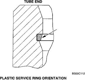
4. Install the plastic service ring into the snap ring
(6). The wide end of the gland (5) should contact
groove in the tube (1).
the piston.
IMPORTANT: See illustration on this page for
6. Do steps 1 through 5 for the other gland (5) and
orientation of the plastic service ring.
piston rod (6).
5. Pull the rod assembly (6) out of the tube (1).
7. Lubricate the seals of the piston rod (6) and the
6. Remove the plastic service ring from the tube
gland (5) with clean oil. Push the piston rod and
(1).
gland sub-assembly into the bore of the tube (1)
far enough to allow the installation of the snap
7. Remove the gland (5) from the rod (6).
ring (4). If necessary, use a soft hammer to drive
8. Fasten the rod (6) in a vise with soft jaws.
the piston rod (6) and gland (5) into the tube (1).
9. Remove the seal (7), ring (8), ring (9), and O-ring
8. Install the snap ring (4) in the tube (1).
(10) from the piston.
9. Pull the rod (6) outwards until the gland (5) is
10. Remove the wiper seal (11), bushing (12), seal
seated against the snap ring (4).
(13), O-ring (14), and backup ring (15) from the
10. Install the spacer (3) on the gland (5).
gland (5).
11. Install the snap ring (2) on the gland (5).
11. Do steps 1 through 10 for the other side.
12. Do steps 7 through 12. for the other side.
Inspection
1. Clean the glands (5), piston rods (6) and tube (1)
in cleaning solvent.
2. Discard the parts that were removed from the
pistons and the glands (5).
3. Illuminate the inside of the tube (1). Inspect the
inside of the tube (1) for deep grooves and other
damage. If there is damage to the tube (1), a
new tube (1) must be used. See section 8001 for
removal of cylinder tube.
4. Remove small scratches on the inside of the
tube (1) with emery cloth of medium grit. Use the
emery cloth with a rotary motion.
5. Check to be sure that the piston rods (6) are
straight. If a piston rod (6) is not straight, install a
new piston rod (6).
Assembly
1. Install the wiper seal (11) in the gland (5). The
lips must be toward the small end of the gland
(5).
H-31
Bur 6-41750
Issued 2-01
Printed in U.S.A.

