
TM 5-2420-230-24-2
Section 1 - Cylinder Block - Group 1
Piston and Connecting Rod - Assembly (1-30)
B Series Shop Manual
Page 1-45
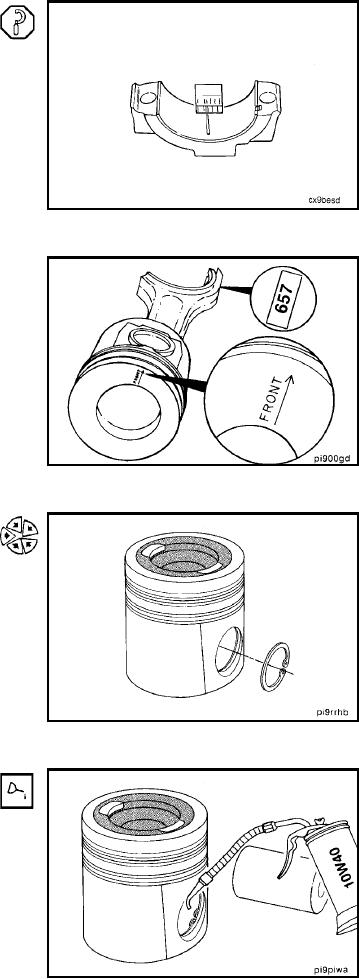
Bearing clearance can also be determined with plastigage
during engine assembly.
Piston and Connecting Rod - Assem-
bly (1-30)
Be sure ``front'' marking on piston and the numbers on
the rod and cap are oriented as illustrated.
NOTE: The numbers shown in the illustration are for ex-
ample purposes only.
Install the retaining ring in the pin groove on the ``front''
side of the piston.
Lubricate the pin and pin bores with engine oil.
L-248