
TM 5-2420-230-24-2
Component Specifications and Torque Values
Section V - Engine Component Specifications - Group 18
Page V-24
B Series
Component or Assembly (Procedure)
Ref.No./Steps
Metric
U.S.
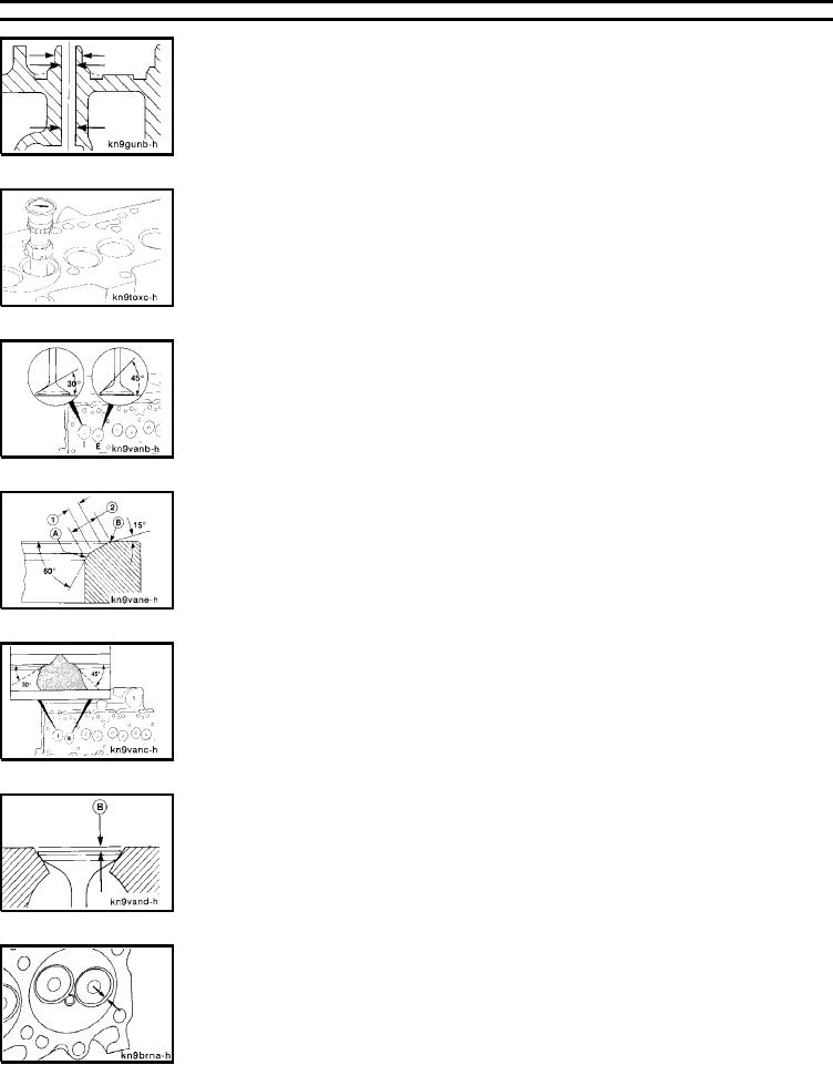
Valve Guide Bore Diameter
8.019 mm
MIN
0.3157 in
8.090 mm
MAX
0.3185 in
Valve Seat-to-Valve Guide Runout
360 Degrees
0.10 mm
MAX
0.004 in
Valve Face Grinding Angle
Intake:
30 degrees
45 degrees
Valve Seat Width Limit
Grind area (A) with a 60 degree stone and
1
1.5 mm
MIN
0.060 in
(B) with a 15 degree stone to center the
2
2.0 mm
MAX
0.080 in
seat on the valve face and obtain the valve
seat width limits.
Valve Seat Grinding Angle
Intake:
30 degrees
45 degrees
Valve Recess in Cylinder Head
B
0.99 mm
MIN
0.039 in
1.52 mm
MAX
0.060 in
Valve Insert Bore Depth (Standard Insert)
10.30 mm
MIN
0.4055 in
10.50 mm
MAX
0.4139 in
L-498