
TM 5-2420-230-24-2
B3.9 and B5.9 Series Engines
Camshaft (001-008)
Section 1 - Cylinder Block - Group 01
Page 1-33
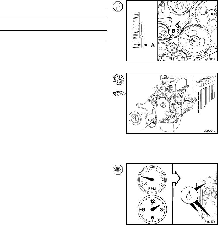
Verify that the camshaft has proper backlash and end play.
Camshaft End Play (A)
mm
in
0.12
MIN
0.005
0.47
MAX
0.018
Camshaft Gear Backlash Limits (B)
mm
in
0.330
MIN
0.013
0.76
MAX
0.030
Complete the installation of the removed parts.
Install the gear cover. Refer to Procedure 001-031.
Install the vibration damper. Refer to Procedure 001-
052.
Install the drive belt. Refer to Procedure 008-002.
Install the tappets. Refer to Procedure 004-015.
Install the push tubes. Refer to Procedure 004-014.
Install the rocker levers. Refer to Procedure 003-
008.
Adjust the valve lash. Refer to Procedure 003-004.
Install the rocker lever cover. Refer to Procedure
003-011.
Install fuel transfer pump. Refer to Procedure 005-
045.
Operate the engine at idle for 5 to 10 minutes, and
check for leaks and loose parts.
L-711