
TM 5-2420-230-24-2
B3.9 and B5.9 Series Engines
Crankshaft (001-016)
Section 1 - Cylinder Block - Group 01
Page 1-53
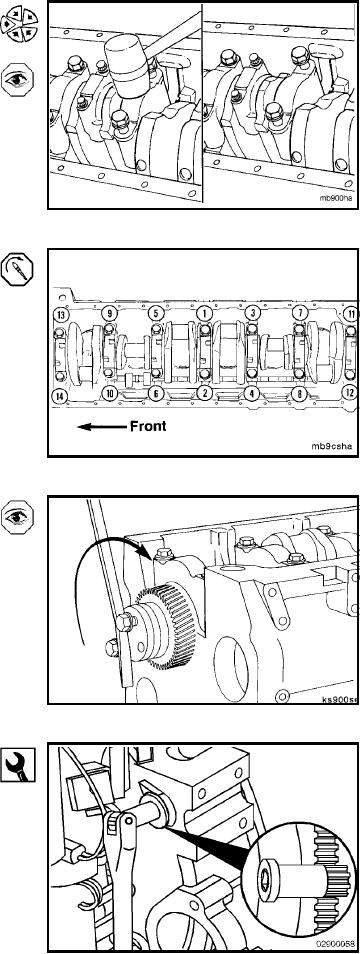
Tap the main bearing cap gently into position.
NOTE: Make sure the main bearing is still aligned with the
cap.
When seated, the main bearing capscrews can be threaded
in by hand.
Tighten the main bearing capscrews evenly following the
illustrated sequence.
Torque Value: Step 1
60 Nm
[44 ft-lb]
2
90 Nm
[66 ft-lb]
3
Turn clockwise 90 degrees
NOTE: The crankshaft must rotate freely after the main
bearings have been installed.
Inspect the main bearing installations and the size of the
main bearings if the crankshaft will not rotate freely.
Rotation Check (001-016-052)
Barring Tool, Part No. 3824591
The barring tool inserts into the flywheel housing and en-
gages the flywheel ring gear. The crankshaft can then be
rotated by hand using a 1/2-inch-drive ratchet or breaker
bar.
L-731