
TM 5-2420-230-24-2
B3.9 and B5.9 Series Engines
Overhead Set (003-004)
Section 3 - Rocker Levers - Group 03
Page 3-5
14-mm Wrench, Flat-Blade Screwdriver
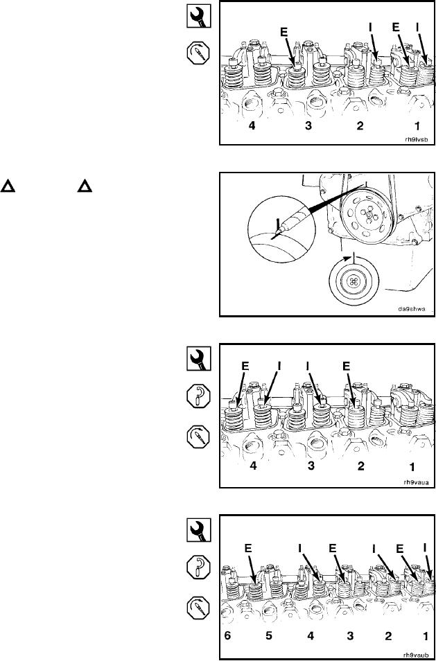
Four-Cylinder Engine Adjustment
Locate top dead center (TDC) for cylinder No. 1.
Set only valves indicated by the arrows (E = exhaust, I =
intake). Do not set valves that are not indicated.
Holding the locknut steady with the wrench, adjust the
valve clearance with the screwdriver or allen wrench.
Tighten the locknut, and measure the valve lash again.
Torque Value: 24 Nm
[18 ft-lb]
CAUTION
To avoid engine or pin damage, be sure the timing pin
is disengaged.
Mark the vibration damper, and rotate the crankshaft 360
degrees.
14-mm Wrench, Flat-Blade Screwdriver, or 5-mm Allen
Wrench
Adjust the valves as indicated in the illustration.
Torque Value: 24 Nm
[18 ft-lb]
Set only valves indicated by the arrows (E = exhaust, I =
intake). Do not set valves that are not indicated.
14-mm Wrench, Flat-Blade Screwdriver
Six-Cylinder Engine Valve Adjustment
Locate top dead center (TDC) for cylinder No. 1.
Set only the valves indicated by the arrows in the illustra-
tion (E = exhaust, I = intake).
Holding the locknut steady with the wrench, adjust the
valve clearence with the screwdriver or allen wrench.
Tighten the locknut, and measure the valve lash again.
Torque Value: 24 Nm
[18 ft-lb]
L-833