
TM 5-2420-230-24-2
Rocker Lever (003-008)
B3.9 and B5.9 Series Engines
Page 3-6
Section 3 - Rocker Levers - Group 03
CAUTION
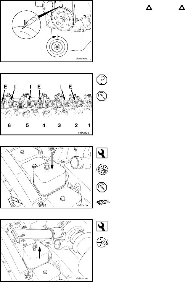
To avoid engine or pin damage, be sure timing pin is
disengaged.
Mark the pulley, and rotate the crankshaft 360 degrees.
Adjust the valves as indicated in the illustration.
Set only the valves indicated by the arrows in the illustra-
tion (E = exhaust, I = intake). Do not set valves that are
not indicated.
Torque Value: 24 Nm
[18 ft-lb]
15 mm
Install the rocker lever covers, and tighten the capscrews.
Torque Value: 24 Nm
[18 ft-lb]
Refer to Procedure 003-011.
Rocker Lever (003-008)
Remove (003-008-002)
15 mm
Remove the rocker lever covers.
L-834