
TM 5-2420-230-24-2
B3.9 and B5.9 Series Engines
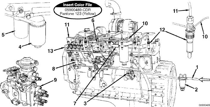
Flow Diagram, Fuel System
Section 5 - Fuel System - Group 05
Page 5-5
Flow Diagram, Fuel System
8. Bosch P7100 injection pump
1. Fuel from supply tank
9. Bosch rotary injection pump
2. Prefilter or screen
10. Fuel drain manifold
3. Fuel lift pump
11. High-pressure fuel line
4. Fuel/water separator
12. Bosch 7-mm closed-nozzle, hole-type injectors
5. Fuel filter
13. Fuel return to supply tank.
6. Low-pressure fuel line
7. Turbocharger boost control line
L-865