
TM 5-2420-230-24-2
Fuel Injection Pump, Rotary (005-014)
B3.9 and B5.9 Series Engines
Page 5-52
Section 5 - Fuel System - Group 05
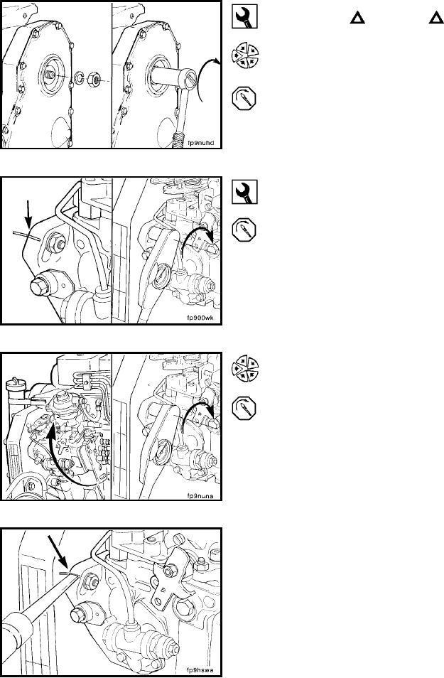
CAUTION
Be sure the timing pin is disengaged before the final
torque step to avoid damage to the timing pin.
22 mm
Install the pump driveshaft nut and spring washer. The
pump will rotate slightly because of gear helix and clear-
ance. This is acceptable provided the pump is free to move
on the flange slots and the crankshaft does not move.
Torque Value: 15 to 20 Nm
[133 to 177 in-lb]
13 mm
If installing the original pump, rotate the pump to align the
scribe marks.
Torque Value: 24 Nm
[18 ft-lb]
If installing a new or rebuilt pump without scribe marks,
take up gear lash by rotating the pump against the direction
of drive rotation. Tighten the flange mounting nuts.
Torque Value: 24 Nm
[18 ft-lb]
Permanently mark the injection pump flange to match the
mark on the gear housing.
L-912