
TM 5-2420-230-24-2
B3.9 and B5.9 Series Engines
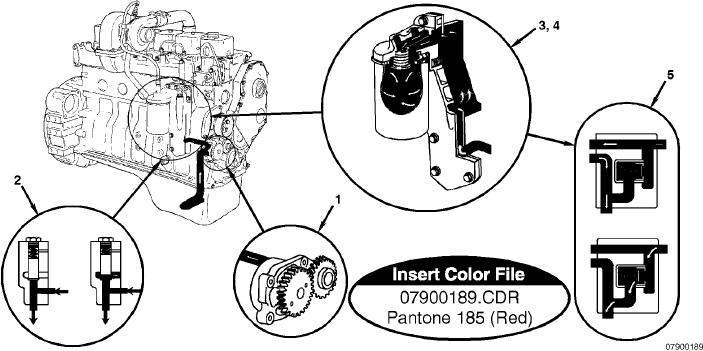
Flow Diagram, Lubricating Oil System
Section 7 - Lubricating Oil System - Group 07
Page 7-3
Flow Diagram, Lubricating Oil System
1. Gerotor lubricating oil pump
4. Full-flow filter
5. Filter bypass valve.
2. Pressure-regulating valve
3. Lubricating oil cooler
Lubricating Oil Pump
The engine uses a gerotor-type lubricating oil pump (1). The machined cavity in the block is the same for all engines.
A wider gerotor is used in the six-cylinder engine to increase the lubricating pump capacity. Consequently, the
four-cylinder and six-cylinder lubricating pumps are not interchangeable.
Pressure-Regulating Valve
The pressure-regulating valve (2) is designed to keep the lubricating oil pressure from exceeding 449 kPa [65 psi]. When
the lubricating oil pressure from the pump is greater than 449 kPa [65 psi], the valve opens, uncovering the dump port,
so part of the lubricating oil is routed to the oil pan. The minimum lubricating oil pressure limit is the same for the
four-cylinder and the six-cylinder engine. Because of manufacturing tolerances of the components and the oil passages,
the lubricating oil pressure can differ as much as 69 kPa [10 psi] between engines.
L-1015